Chapter 3 Replacing Assemblies
Removing the Bumpers
3-4
Assembly Level Service Guide
3
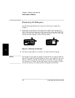
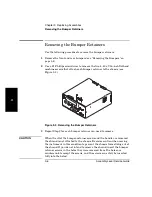
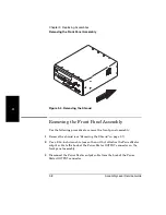
Removing the Bumpers
Use the following procedure to remove the front and rear protective
bumpers:
1
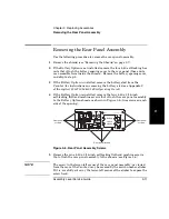
Remove the rear bumper by lifting the inner edge of the bumper away
from the shroud near one corner at the top and one side and pulling that
corner away from the instrument. Repeat the process with the remaining
corners until the bumper is free of the instrument.
Figure 3-1. Removing the Bumpers
2
Use the same procedure (as in Step 1) to remove the front bumper.
NOTE
The bumpers can be used to support and protect the instrument after the
shroud is removed. Place both bumpers on their inner edges on your work
surface, and then place the instrument on top of them. The rear bumper
can also serve as a holder for the instrument (once the bumper retainers
are removed) when you need to position it upright on either end.
OPTIONS
001 Oven Time Base
002 Battery
Main Power
!
!
In or Out
Reference 10 MHz
Auxiliary
AC POWER
90-130 VAC 50/60/400 Hz
190-230 VAC 50/60 Hz
FUSE
1.5A T
250V
WARNING:
To avoid electrical shock:
Do not remove covers.
No user serviceable parts inside.
Refer all servicing to qualified personnel.
RS-
232
GPIB
Agilent
Counter/ Power Meter/ DVM
This unit must be earth grounded.
Made in U.S.A.
of domestic and foreign content
POWER METER
POWER
GHz
MHz
kHz
Hz
20 GHz Counter/Power Meter/DVM
MODIFY
Reset/
Local
Cal
Factor
Freq
Offset
Menu
On/Off
Enter
Avg
+ / -
Freq
Clear
Resol
Shift
Ch 12
Rel Freq
Offset
Avg On
Rel Pwr
Offset
dB
dBm
Watts
mW
uW
%
Ext Rel
Error
Shift
Hold
Rate Rmt SRQ
Standby
Counter
Power
Meter
DVM
Rate
Pwr
Offset
Display
Power
dBm/W
Store
Cal
Zero
Offset
On/Off
Rel Pwr
DVM
+
–
DAMAGE
±60 VDC
Display
DVM
POWER METER
OUTPUT
Power Ref.
1.00mW 50MHz
INPUT
Do NOT Exceed
Sensor Max Power
COUNTER
Offset
On/Off
Rel Freq
Chan
Select
COUNTER
CHANNEL 1
10 Hz to 125 MHz
DAMAGE
+30 dBm
1M
Ω
COUNTER
CHANNEL 2
50MHz to 26.5 GHz
50
Ω
DAMAGE
+27 dBm
Gate
Summary of Contents for 53147A
Page 6: ...Contents vi Assembly Level Service Guide ...
Page 13: ...1 Performance Tests Verifying Specifications ...
Page 55: ...2 Service ...
Page 88: ...Chapter 2 Service Troubleshooting the Instrument 2 34 Assembly Level Service Guide 2 ...
Page 89: ...3 Replacing Assemblies Disassembly and Reassembly ...
Page 104: ...Chapter 3 Replacing Assemblies Removing the Power Supply 3 16 Assembly Level Service Guide 3 ...
Page 105: ...4 Replaceable Parts ...
Page 116: ...Chapter 4 Replaceable Parts Parts Identification 4 12 Assembly Level Service Guide 4 ...
Page 117: ...5 Backdating ...
Page 119: ...6 Specifications ...
Page 125: ...A Rack Mounting the Instrument ...
Page 134: ...Index Index 4 Assembly Level Service Guide Index ...

