Chapter 2 Operating Your Frequency Counter
Using the MEASURE Menu Keys
2-12
Operating Guide
2
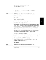
To Measure Frequency
1
Connect power source to Counter, and turn on Counter.
All segments of the front-panel display will light up while the Counter performs its
power-on self-test, and then dashes are displayed. The Counter is now ready to
measure frequency of a signal applied to CHANNEL 1 input. Note that the Freq and
Ch1 annunciators light.
2
Connect an input signal to CHANNEL 1.
The Counter should automatically display the measured frequency of the input signal.
The trigger levels are set to the 50% points of the signal. However, you may disable
auto triggering, and change the trigger levels and slopes.
To set up CHANNEL 1’s coupling, impedance, and triggering conditions to match the
input signal you are trying to measure, refer to the procedures “To Select Input
Coupling and Impedance” and “To Set Input Channel Trigger Level/Sensitivity” in
Chapter 1, “Getting Started,” or the section titled “Using CHANNEL 1 Input
Conditioning Keys” in this chapter.
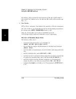
3
To measure the frequency of a signal applied to the optional CHANNEL 2 input,
press Freq Ch2 key.
FREQUENCY 2
will be momentarily displayed and the Freq and Ch2 annunciators
will light. The Counter will be ready to measure the frequency of a signal applied to
CHANNEL 2 input.
Note that the Frequency 2 menu item is not available in Counters that do not contain
the optional Channel 2.
Summary of Contents for 53181A
Page 2: ...NOTES...
Page 14: ...Contents x Operating Guide...
Page 24: ...Preface xx Operating Guide...
Page 33: ...1 Getting Started...
Page 68: ...Chapter 1 Getting Started Making Measurements 1 36 Operating Guide 1...
Page 69: ...2 Operating Your Frequency Counter Operator s Reference...
Page 143: ...3 Specifications...
Page 160: ...Chapter 3 Specifications Introduction 3 18 Operating Guide...


