background image

6- 7

Replacing Assemblies

To remove the front panel

To remove the front panel

1

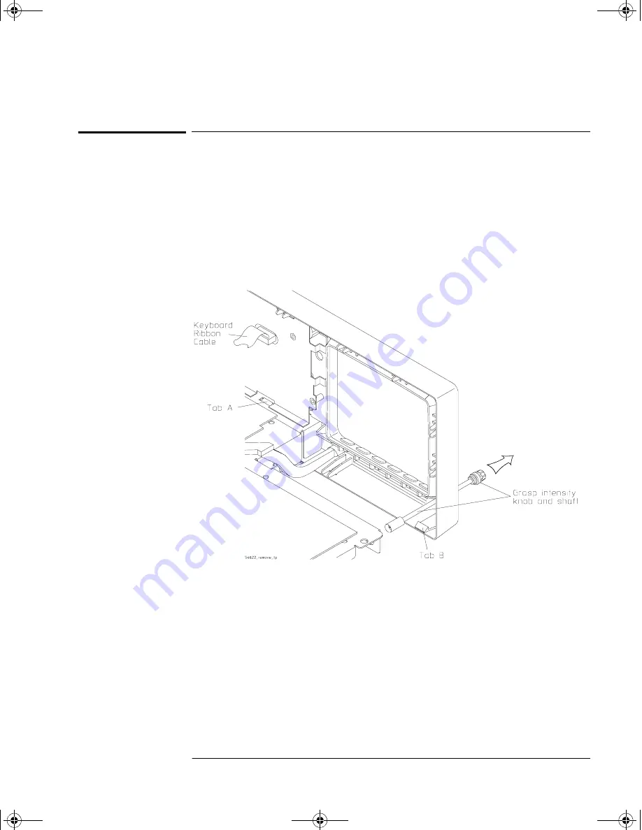
Remove the intensity knob and shaft by grasping the knob with one 
hand and the grasping the shaft behind the front panel with the other 
hand and pulling the shaft straight out from the front panel.

2

Disconnect the keyboard ribbon cable W2 from the keyboard.

3

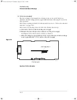
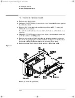
Use a screwdriver to release retainer tab A, and your finger to release 
retainer tab B. See the tab locations in Figure 6-4.

Figure 6-4

Removing the intensity shaft and front panel

4

Swing the front panel out until the bottom clears the deck assembly, 
then lift it up to free the hooks on top and pull it away from the deck.

When installing the front panel, make sure that the power switch shaft is aligned 
with the connection hole in the front panel to make a proper connection. 

Before engaging the retainer tabs, make sure that all of the hooks on top of the 
front panel are fully engaged with their connection holes in the sheet metal. 
Then swing the front panel in to engage the two retainer tabs. 

service.book  Page 7  Wednesday, August 28, 2002  3:25 PM

Summary of Contents for 54641A

Page 1: ...y Information and Regulatory information see the pages at the end of this book Copyright Agilent Technologies 2002 All Rights Reserved Agilent 54641A 42A Oscilloscopes and Agilent 54641D 42D Mixed Signal Oscilloscopes service book Page i Wednesday August 28 2002 3 25 PM ...

Page 2: ...nt configurations or previous results Autoscale performs simple one button setup of the oscilloscope HorizontalControlsselectsweepspeed and delay parameters Sweep speeds from 1 ns div to 50 s div Delay control moves waveform display to point of interest Delayed mode and delay allow zooming in to show a portion of waveform in detail split screen Run control keys begin and end data acquisition Run S...

Page 3: ...e oscilloscope for use Chapter 3 gives performance tests Chapter 4 covers calibration and adjustment procedures Chapter 5 provides troubleshooting information Chapter 6 gives the procedures and techniques for replacing assemblies and other parts Chapter 7 includes a list of replaceable parts part ordering information and shipping information At the back of the book you will find Safety information...

Page 4: ...iv service book Page iv Wednesday August 28 2002 3 25 PM ...

Page 5: ... the oscilloscope interface 2 15 Using Quick Help 2 17 Selecting a language for Quick Help when the oscilloscope starts up 2 17 Selecting a language for Quick Help after you have been operating the oscilloscope 2 18 Loading an updated language file from floppy disk 2 19 Cleaning the oscilloscope 2 20 3 Testing Performance List of Test Equipment 3 3 To construct the test connector 3 4 To test the 5...

Page 6: ...lloscope 5 6 To construct your own dummy load 5 7 To check out the oscilloscope 5 8 To check the Low Voltage Power Supply 5 11 To run the internal self tests 5 13 6 Replacing Assemblies To remove the cabinet 6 4 To remove the fan 6 5 To remove the floppy drive 6 6 To remove the front panel 6 7 To remove the display 6 8 To remove the system board 6 10 To remove the power supply 6 12 To remove the k...

Page 7: ...1 General Information ...

Page 8: ...1 2 General Information This chapter lists general information for the Agilent 54640 series Oscilloscopes It also includes performance characteristics and specifications for the oscilloscopes ...

Page 9: ...641D or 42D Accessory pouch and front panel cover Power cord see table 1 3 IntuiLink for 54600 series Oscilloscopes software and RS 232 cable IntuiLink is a Windows application that makes it very easy for you to download images waveform data or oscilloscope setups from the oscilloscope to your pc using either Microsoft Word or Microsoft Excel After installation of IntuiLink a tool bar in these Mic...

Page 10: ... of points to download It provides the following functionality Download waveform data and display the data as a simple chart Save the data as binary or text files Copy the chart and a selected portion of the data to the clipboard The maximum data saved to the clipboard is 50 000 point Load saved waveform data back into the application Inspect the oscilloscope If there is mechanical damage or a def...

Page 11: ...robe ground lead qty 5 5090 4833 Grabber qty 20 54640 Series Oscilloscope 54620 68701 digital probe kit 54641D 42D only The following additional replacement parts not included are available for the digital cable 5959 9333 replacement probe leads qty 5 5959 9335 replacement pod grounds qty 5 01650 94309 package of probe labels IntuiLink for 54600 series software Data Capture software and serial cab...

Page 12: ...ssoriesavailable for the 54640 Series Oscilloscopes are listed in tables 1 1 am 1 2 Contact your Agilent Sales Office for a complete list of options and accessories Table 1 1 Options available Option Description 003 Shielding Option for use in severe environments or with sensitive devices under test shields both ways in and out RS 03 magnetic interface shielding added to CRT and RE 02 display shie...

Page 13: ...PIB cable 1 m long 34398A RS 232 cable standard with 100 MHz models E2613B 0 5 mm Wedge probe adapter 3 signal qty 2 E2614A 0 5 mm Wedge probe adapter 8 signal qty 1 E2615B 0 65 mm Wedge probe adapter 3 signal qty 2 E2616A 0 65 mm Wedge probe adapter 8 signal qty 1 E2643A 0 5 mm Wedge probe adapter 16 signal qty 1 E2644A 0 65 mm Wedge probe adapter 16 signal qty 1 N2726A Accessory pouch and front ...

Page 14: ...20 1703 Opt 918 Japan 8120 4754 Opt 901 Australia 8120 0696 Opt 919 Israel 8120 6799 Opt 902 Europe 8120 1692 Opt 920 Argentina 8120 6871 Opt 903 U S A 8120 1521 Opt 921 Chile 8120 6979 Opt 906 Switzerland 8120 2296 Opt 922 China 8120 8377 Opt 912 Denmark 8120 2957 Opt 927 Thailand 8120 8871 Opt 917 Africa 8120 4600 ...

Page 15: ...Max Memory Depth 8 MB interleaved 4 MB each channel Vertical Resolution 8 bits Peak Detection 1 ns max sample rate Averages selectable from 2 4 8 16 32 64 to 16383 High Resolution Mode 12 bits of resolution when 100 us div average mode with average 1 Filter Sinx x interpolation single shot BW sample rate 4 or bandwidth of scope whichever is less with vectors on Acquisition Digital Channels on 5464...

Page 16: ...ms with 50 ohm input Offset Range 5 V on ranges 10 mV div 20 V on ranges 10 mV div to 200 mV div 75 V on ranges 200 mV div Dynamic Range Lesser of 8 div or 32 V Input Resistance 1 MΩ 1 50 ohm selectable Input Capacitance 13 pF Coupling ac dc BW Limit 25 MHz selectable Channel to Channel Isolation with channels at same V div DC to max bandwidth 40 dB Probes 10 1 10073C shipped standard for each ana...

Page 17: ...o 10 mV div 80 mV full scale 5 mV offset accuracy 2 0 80 mV 0 4 80 mV 1 92 mV 1 2 mV div is a magnification of 4 mV divsetting For vertical accuracycalculations use fullscale of32mV for 2 mV divsensitivitysetting Vertical System Digital Channels 54641D and 54642D only Number of Channels 16 Digital labeled D15 D0 Threshold Groupings Pod 1 D7 D0 Pod 2 D15 D8 Threshold Selections TTL CMOS ECL user de...

Page 18: ...1 50 us 20 ps 50 52 ns 0 005 reading 0 1 screen width 40 ps Digital Delta t Accuracy Same Channel Channel to Channel non Vernier settings 0 005 reading 0 1 screen width 1 digital sample period 1 ns Example for signal with pulse width of 10 us scope set to 5 us div 50 us screen width and single pod active 1 GSa s delta t accuracy 005 10 us 0 1 50 us 1 ns 51 5 ns 0 005 reading 0 1 screen width 1 dig...

Page 19: ... frame with address and or data values Also trigger on Missing Acknowledge Restart EEPROM read and 10 bit write LIN TriggeronLIN LocalInterconnectNetwork syncbreakatbeginningofmessageframe Sequence Find event A trigger on event B with option to reset on event C or time delay SPI Trigger on SPI Serial Peripheral Interface a data pattern during a specific framing period Support positive and negative...

Page 20: ...ng Input Resistance 1 MΩ 3 or 50 Ohm Input Impedance 13 pF Maximum Input CAT I 300 Vrms 400 Vpk CAT II 100 Vrms 400 Vpk with 10073C 10 1 probe CAT I 500 Vpk CAT II 400 Vpk 5 Vrms with 50 ohm input Range DC coupling trigger level 8 V AC coupling LF reject AC input minus trigger level not to exceed 8 V Sensitivity DC to 100 MHz 100 mV 100 MHz to max bandwidth 200 mV Coupling ac 3 5 Hz dc noise rejec...

Page 21: ... Peak to Peak Maximum Minimum Average Amplitude Top Base Overshoot Preshoot RMS dc Time Frequency Period Width Width and Duty Cycle on any channels Rise time Fall time X at Max Time at max volts X at Min Time at min volts Delay and Phase on analog channels only Counter Built in 5 digit frequency counter on any channel Counts up to 125 MHz Threshold Definition Variable by percent and absolute value...

Page 22: ...ues in CSV format Recalled I O RS 232 serial standard port 1 port XON or DTR 8 data bits 1 stop bits parity none 9600 19200 38400 57600 baud rates Parallel standard port Printer support Printer Compatibility HP DeskJet HP LaserJet with HP PCL 3 or greater compatibility Compatibility black and white 150x150 dpi gray scale 600x600 dpi Epson black and white 180x180 dpi Seiko DPU 414 black and white O...

Page 23: ... Non operating 51 C to 71 C Humidity Operating 95 RH at 40 C for 24 hr Non operating 90 RH at 65 C for 24 hr Altitude Operating to 4 570 m 15 000 ft Non operating to 15 244 m 50 000 ft Vibration HP Agilent class B1 and MIL PRF 28800F Class 3 random Shock HP Agilent class B1 and MIL PRF 28800F operating 30 g 1 2 sine 11 ms duration 3 shocks axis along major axis Total of 18 shocks Pollution degree2...

Page 24: ...1 18 ...

Page 25: ...2 Preparing the Oscilloscope for Use service book Page 1 Wednesday August 28 2002 3 25 PM ...

Page 26: ...djust the handle power on the oscilloscope adjust the display intensity connect the oscilloscope probes connect the digital probes with 54641D and 54642D connect a printer connect a RS 232 cable verify basic oscilloscope operation get started using the oscilloscope interface learn how to use Quick Help This chapter also tells you how to clean the oscilloscope service book Page 2 Wednesday August 2...

Page 27: ...hat you have When using the Agilent 54641A and 54642A 2 channel Oscilloscopes you will connect and use analog probes to examine analog signals When using the Agilent 54641D and 54642D Mixed Signal Oscilloscopes you will connect and use both analog and digital probes to examine analog and digital signals Analog channels 2 Analog channels 2 Digital channels 16 service book Page 3 Wednesday August 28...

Page 28: ...ent and pull the pivot out until it stops 2 Without releasing the pivots swivel the handle to the desired position Then release the pivots Continue pivoting the handle until it clicks into a set position 54622D MIXED SIGNAL OSCILLOSCOPE CHANNEL INPUTS 5ns 1 s 15 0 Time Div Select Agilent service book Page 4 Wednesday August 28 2002 3 25 PM ...

Page 29: ...adjusts for input line voltages in the range 100 to 240 VAC Therefore you do not need to adjust the input line voltage setting The line cord provided is matched to the country of origin Ensure that you have the correct line cord See table 1 3 2 Press the power switch Some front panel key lights will come on and the oscilloscope will be operational in about 5 seconds 5V T rigger out service book Pa...

Page 30: ...waveform intensity rotate the Intensity control counter clockwise To increase waveform intensity rotate the Intensity control clockwise Intensity control The grid or graticule intensity on the display can be adjusted by pressing the Display key then turn the Entry knob labeled on the front panel to adjust the Grid control Dim Bright service book Page 6 Wednesday August 28 2002 3 25 PM ...

Page 31: ...ed However the inputs could still be damaged depending on the time constant of the signal C A U T I O N The 50Ω input protection mode only functions when the oscilloscope is powered on 1 Connect the Agilent 10073C 1 5 meter 10 1 oscilloscope probe to the analog channel 1 or 2 BNC connector input on the oscilloscope Maximum input voltage for analog inputs in 1 MΩ impedance mode CAT I 300 Vrms 400 V...

Page 32: ...be can introduce measurement errors To compensate a probe follow these steps 1 Connect the probe from channel 1 to the Probe Comp signal on the lower right corner of the front panel 2 Press Autoscale 3 Use a nonmetallic tool to adjust the trimmer capacitor on the probe for the flattest pulse possible comp cdr Perfectly compensated Over compensated Under compensated service book Page 8 Wednesday Au...

Page 33: ...accidentally short two lines together while connecting probes You can leave the oscilloscope powered on because no voltage appears at the probes 2 Connect the digital probe cable to D15 D0 connector on the front panel of the mixed signal oscilloscope The digital probe cable is indexed so you can connect it only one way You do not need to power off the oscilloscope Use only the Agilent part number ...

Page 34: ...scilloscope only 3 Connect a grabber to one of the probe leads Be sure to connect the ground lead Other probe leads are omitted from the figure for clarity 4 Connect the grabber to a node in the circuit you want to test Grabber service book Page 10 Wednesday August 28 2002 3 25 PM ...

Page 35: ...rabber to the ground lead and attach the grabber to ground in the circuit under test 6 Connect the ground lead on each set of channels using a probe grabber The ground lead improves signal fidelity to the instrument ensuring accurate measurements Signal Lead Ground Lead Grabber Circuit Ground Channel Pod Ground service book Page 11 Wednesday August 28 2002 3 25 PM ...

Page 36: ... of interest 8 If you need to remove a probe lead from the cable insert a paper clip or other small pointed object into the side of the cable assembly and push to release the latch while pulling out the probe lead Replacement parts are available See the Replaceable Parts chapter for details Signals Ground service book Page 12 Wednesday August 28 2002 3 25 PM ...

Page 37: ... Utilities chapter in the User s Guide To connect an RS 232 cable The oscilloscope can be connected to a controller or a PC through the RS 232 connector on the rear of the oscilloscope An RS 232 cable is shipped with each 54642A 42D oscilloscope and may be purchased for the 54641A 41D oscilloscopes 1 Attach the 9 pin D connector on the RS 232 cable to the RS 232 connector on the rear of the oscill...

Page 38: ...ss the Default Setup softkey under the display The oscilloscope is now configured to its default settings 4 Press the Autoscale key on the front panel You should then see a square wave with peak to peak amplitude of about 5 divisions and a period of about 4 divisions as shown below If you do not see the waveform ensure your power source is adequate the oscilloscope is properly powered on and the p...

Page 39: ...e oscilloscope interface When the oscilloscope is first turned on a startup screen is displayed as shown below This menu is only accessible when the oscilloscope first starts up service book Page 15 Wednesday August 28 2002 3 25 PM ...

Page 40: ...list of choices Repeatedly press the softkey until your choice is selected Use the Entry knob labeled or press the softkey to adjust the parameter Option is selected and operational Feature is on Press the softkey again to turn the feature off Feature is off Press the softkey again to turn the feature on Links you to another menu Press the softkey to view the menu Press the softkey to return to th...

Page 41: ...g the message Releasing the key returns the oscilloscope to the previous state Selecting a language for Quick Help when the oscilloscope starts up When the oscilloscope first powers up you can press the Language softkey to select a language for viewing Quick Help Successively press the Language softkey until the desired language in the list is selected You can also select language later from the U...

Page 42: ...illoscope 1 Press the Utility key then press the Language softkey to display the Language menu 2 Press the Language softkey until the desired language in the list is selected When updates occur an updated language file can be downloaded from www agilent com find 5464xsw or call an Agilent center and request a language disk for your instrument service book Page 18 Wednesday August 28 2002 3 25 PM ...

Page 43: ...r instrument 1 Insert the floppy disk with the language file into the floppy disk drive on the oscilloscope 2 Press the Utility key then press the Language softkey to display the Language menu 3 Press the Load Languages softkey to load the updated language file into the oscilloscope 4 Press the Language softkey and select the language to be viewed For more information about loading languages refer...

Page 44: ...leaning the oscilloscope Water can enter the front panel keyboard control knobs or floppy disk damaging sensitive electronic components 2 Clean the oscilloscope with a soft cloth dampened with a mild soap and water solution 3 Make sure that the instrument is completely dry before reconnecting to a power source service book Page 20 Wednesday August 28 2002 3 25 PM ...

Page 45: ...3 Testing Performance service book Page 1 Wednesday August 28 2002 3 25 PM ...

Page 46: ... is used in the digital channel threshold accuracy test Let the Equipment Warm Up Before Testing Foraccuratetestresults let the test equipment and the oscilloscope warm up 30 minutes before testing Verifying Test Results During the tests record the readings in the Performance Test Record at the end of this chapter for your oscilloscope To verify whether a test passes verify that the reading is wit...

Page 47: ...y Agilent 01660 63801 Digital Multimeter 0 1 mV resolution 0 0005 accuracy Agilent 34401A Power Splitter Outputs differ by 0 15 dB Agilent 11667B Power Supply DC offset voltage of 5 5 V to 35 5 V 0 1 mV resolution Agilent 3245A Oscilloscope Calibrator 25 MHz 500 MHz sine wave 5 ppm Fluke 5820A BNC banana cable Agilent 11001 60001 BNC cable qty 3 Agilent 10503A Probe cable Agilent 01650 61607 Short...

Page 48: ... one side of the Berg strip solder a jumper wire to all of the pins 3 On the other side of the Berg strip solder another jumper wire to all of the pins 4 Solder the center of the BNC connector to a center pin on one of the rows on the Berg strip 5 Solder the ground tab of the BNC connector to a center pin on the other row on the Berg strip Figure 3 1 Constructing the 8 by 2 Connector Construct Tes...

Page 49: ...nel 3 Press the Autoscale key If four square waves appear the acquisition system is functioning correctly If the square waves do not appear go to the Troubleshooting chapter Then return here to finish testing the digital channels 4 Disconnect the digital channels from Probe Comp 5 Use steps 2 and 3 to test the following sets of digital channels After you test one set of digital channels removethem...

Page 50: ...a test passes verify that the voltage reading iswithin the limits in the Performance Test Record Table 3 2 Equipment Required to Test Threshold Accuracy Test Threshold Accuracy only on the 54641D 42D Mixed Signal Oscilloscope You need to perform these instructions only if you will be testing the Agilent 54641D 42D Mixed Signal Oscilloscope Equipment Critical Specifications Recommended Model Part D...

Page 51: ...r method 1 or method 2 described in the following to connect the digital channels for testing a Method 1 Using the Test Connector Use the 8 by 2 test connector and the BNC cable assembly to connect digital channels D0 D7 to one side of the BNC Tee Then connect the D0 D7 ground lead to the ground side of the 8 by 2 connector See figure 3 2 Figure 3 2 Setting Up Equipment and Test Connector for the ...

Page 52: ...gure 3 3 Setting Up Equipment and Test Fixture for the Threshold Test 4 Use a BNC banana cable to connect the multimeter to the other side of the BNC Tee 5 Connect the BNC Tee to the Channel 1 output of the calibrator as shown in figure 3 2 and figure 3 3 6 On the oscilloscope press the D7 Thru D0 key then press the Threshold softkey 42thresh2 cdr HP34401A 01660 63801 Test Fixture BNC Banana cable...

Page 53: ...librator voltage in the performance test record d Use the knob on the oscilloscope calibrator to increase the offset voltage in increments of 10 mV until the activity indicators for digital channels D7 D0 are all at digital high levels Record the oscilloscope calibrator voltage in the performance test record Before proceeding to the next step make sure that you have recorded the oscilloscope calib...

Page 54: ...e 3 4 Equipment Required to Verify Voltage Measurement Accuracy Do this procedure first for Channel 1 Then repeat the procedure for Channel 2 1 Set up the oscilloscope a Adjust the channel 1 position knob to place the baseline at 0 5 division from the bottom of the display Equipment Critical Specifications Recommended Model Part Power supply 14 mV to 35 Vdc 0 1 mV resolution Fluke 5820A or Agilent...

Page 55: ...nel to set the Y1 cursor on the baseline of the signal Volts Div Setting Power Supply Setting Test Limits 5 V Div 35 V 34 04 V to 35 96 V 2 V Div 14 V 13 616 V to 14 384 V 1 V Div 7 V 6 808 V to 7 192 V 0 5 V Div 3 5 V 3 404 V to 3 596 V 0 2 V Div 1 4 V 1 3616 V to 1 4384 V 0 1 V Div 700 mV 680 8 mV to 719 2 mV 50 mV Div 350 mV 340 4 mV to 359 6 mV 20 mV Div 140 mV 136 16 mV to 143 84 mV 10 mV Div...

Page 56: ...n the test limits see the Troubleshooting chapter Then return here 6 Continue to check the voltage measurement accuracy with the remaining Volts div setting values in Table 3 5 7 When you are finished checking all of the power supply setting values disconnect the power supply from the oscilloscope 8 Repeat this procedure for Channels 2 Figure 3 4 Using a Blocking Capacitor to Reduce Noise Use a Bl...

Page 57: ...t 2 mV div to 5 V div All channels 3 dB dc to 500 MHz ac coupled 3 5 Hz to 500 MHz 54641A and 54641D Test limits at 2 mV div to 5 V div All channels 3 dB dc to 350 MHz ac coupled 3 5 Hz to 350 MHz Table 3 6 Equipment Required to Verify Bandwidth Equipment Critical Specifications Recommended Model Part Oscilloscope Calibrator Fluke 5820A Cable Type N m 24 inch Agilent 11500B The oscilloscope calibr...

Page 58: ...w seconds for the measurement to settle averaging is then complete View the Pk Pk reading at the bottom of the display Record the reading Vp p _______ V 7 Change the frequency of the signal generator to the value shown below for your instrument Table 3 7 Signal Generator Frequency Setting 8 Change the time base to 5 ns div a Wait a few seconds for the measurement to settle b View the Pk Pk reading...

Page 59: ... and Imped to 50 Ohm b Press the Display key then set the Vectors softkey to off c Press the Autoscale key d Set the time base to 20 µs div e Press the Main Delayed key then set the Time Ref softkey to Left f Adjust the Trigger Level knob to obtain a stable display 3 Press the Quick Meas softkey set the Source softkey to 1 then select and measure Frequency and Period Measure the following Frequenc...

Page 60: ...the trigger level to obtain a stable display 7 Measure the following Frequency 500 MHz The test limits are 492 6 MHz to 507 6 MHz Period 2 ns The test limits are 1 970 ns to 2 030 ns If the measurements are not within the test limits see the Troubleshooting chapter Then return here 54641A and 54641D only 8 Change the calibrator to 2 857 ns markers Change the time base to 1 ns div Adjust the trigge...

Page 61: ...ter of 1 div or 5 mVp p 10 mV div dc to max bandwidth 0 6 div Test limits for the External trigger dc to 100 MHz 100 mVp p 100 MHz to max bandwidth 200 mVp p Table 3 9 Equipment Required to Verify Trigger Sensitivity Equipment Critical Specifications Recommended Model Part Oscilloscope Calibrator 25 MHz 100 MHz 350 MHz and 500 MHz sine waves Fluke 5820A Power splitter Outputs differ 0 15 dB Agilen...

Page 62: ...test still passes If adjusting the trigger does not help see the Troubleshooting chapter Then return here f Record the result as Pass or Fail in the Performance Test Record 4 Verify the trigger sensitivity at maximum bandwidth and 10 mV div division a Change the output of the calibrator to 500 MHz for the 54642A 42D or 350 MHz or the 54641A 41D and set the amplitude to about 100 mVp p b Set the ti...

Page 63: ...calibrator to 500 MHz for the 54642A 42D or 350 MHz for the 54641A 41D and set the amplitude to 400 mVp p The power splitter divides the 400 mVp p so that 200 mVp p is applied to each of the oscilloscope inputs 4 Press the Autoscale key 5 Press the Trigger Edge key then press the Ext softkey to set the trigger source to external trigger 6 Check for stable triggering and adjust the trigger level if...

Page 64: ...______ ________ 200 mV Div 1 4 V 1 3616 V to 1 4384 V ________ ________ 100 mV Div 700 mV 680 8 mV to 719 2 mV ________ ________ 50 mV Div 350 mV 340 4 mV to 359 6 mV ________ ________ 20 mV Div 140 mV 136 16 mV to 143 84 mV ________ ________ 10 mV Div 70 mV 68 08 mV to 71 92 mV ________ ________ 5 mV Div 35 mV 34 04 mV to 35 96 mV ________ ________ 2 mV Div 14 mV 13 232 mV to 14 768 mV ________ _...

Page 65: ...____ ________ 200 mV Div 1 4 V 1 3616 V to 1 4384 V ________ ________ 100 mV Div 700 mV 680 8 mV to 719 2 mV ________ ________ 50 mV Div 350 mV 340 4 mV to 359 6 mV ________ ________ 20 mV Div 140 mV 136 16 mV to 143 84 mV ________ ________ 10 mV Div 70 mV 68 08 mV to 71 92 mV ________ ________ 5 mV Div 35 mV 34 04 mV to 35 96 mV ________ ________ 2 mV Div 14 mV 13 232 mV to 14 768 mV ________ ___...

Page 66: ...3 22 service book Page 22 Wednesday August 28 2002 3 25 PM ...

Page 67: ...4 Calibrating and Adjusting service book Page 1 Wednesday August 28 2002 3 25 PM ...

Page 68: ...alibration temperature if you want to maximize the measurement accuracy The amount of use environmental conditions andexperiencewith other instruments help determine if you need shorter adjustment intervals In this chapter you will Adjust the power supply Perform self calibration Adjust the display Let the Equipment Warm Up Before Adjusting Beforeyou startthe adjustments letthe oscilloscope and te...

Page 69: ...damage to the oscilloscope can occur C A U T I O N USE EXTERNAL FAN TO REDUCE TEMPERATURE When you must operate the oscilloscope with its cover removed use an external fan to provide continuous air flow over the samplers Air flow over the samplers is reduced when the cover is removed which leads to higher than normal operating temperatures Have the fan blow air across the system PC board where the...

Page 70: ...er Supply 1 Prepare the oscilloscope for the voltage adjustment a Turn off the oscilloscope and disconnect the power cable b Remove the oscilloscope cover For a list of parts see the Replaceable Parts chapter then return here c Place the oscilloscope on its side d Connect the negative lead of the digital multimeter to a ground point on the oscilloscope chassis e Reconnect the power cable f Turn on...

Page 71: ...s on the bottom of the oscilloscope 3 Make sure that the voltage measurements are within the tolerances listed in Table 4 2 Table 4 2 Power Supply Voltage Tolerances E 9 9 9 9 Supply Voltage Tolerance 5 1 V 250 mV 4 85 V to 5 35 V 5 2 V 156 mV 5 04 V to 5 36 V 15 75 V 1 260 V 787 mV 14 963 V to 17 010 V 3 4 V 100 mV 3 30 V to 3 50 V 8 2 V 82 mV 8 12 V to 8 28 V measure at Printer Power connector o...

Page 72: ...stment location is on the power supply as shown below Figure 4 2 Low Voltage Power Supply Adjustments on the top of the oscilloscope 5 If adjusting the power supply does not bring all the voltages within tolerance go to the Troubleshooting chapter 5 E Fan Connector 3 4V Adjustment service book Page 6 Wednesday August 28 2002 3 25 PM ...

Page 73: ... should be performed at least once a year any time the ambient temperature of the oscilloscope has changed more than 10 C since the last User Cal or after any repair Performing User Cal will not invalidate your Certificate of Calibration Successful completion of User Cal does not certify this oscilloscope with a National Institute of Standards and Technology NIST calibration 1 Disconnect all input...

Page 74: ...ft on the front panel to approximately 50 When to Adjust the Oscilloscope Display The oscilloscope display normally does not require adjustment However when it is obvious that the display is out of adjustment use this optional procedure Equipment Critical Specifications Recommended Model Part Digital multimeter Accuracy 0 05 1 mV resolution Agilent 34401A V HOLD vertical hold INTENSITY intensity c...

Page 75: ... the half bright borders equally 8 Adjust V SIZE vertical size to center the display vertically at the maximum allowable size without losing the half bright borders Because V LIN and V SIZE interact with each other you may need to re adjust the sizing and vertical centering of the pattern on the display Figure 4 3 Oscilloscope Display Board Adjustments 68 57 2 86 9 2 9 6 9 1 XVH E 5 2 service book...

Page 76: ...4 10 service book Page 10 Wednesday August 28 2002 3 25 PM ...

Page 77: ...5 Troubleshooting service book Page 1 Wednesday August 28 2002 3 25 PM ...

Page 78: ... solving suggestions The troubleshooting section shows you how to Check out the oscilloscope Clear error messages from the display Check the low voltage power supply Run internal self tests Using the Dummy Load Before you begin troubleshooting you must either already have the dummy load that is mentioned or you must construct one as described in this chapter You will use this dummy load while trou...

Page 79: ...and that the INTENSITY knob is adjusted correctly If there is no display go to the troubleshooting procedures in this chapter Check that the oscilloscope probe lead wires are securely inserted into the connector assembly and that the probe clips make good contact with the probe lead wires Check that the probe clips are securely connected to points in the circuit under test and that the ground is c...

Page 80: ...ct signals in the circuit under test Check to see that the ground lead on the cable is securely connected to ground inthecircuitunder test For high speedmeasurements each probe s individual ground lead should also be connected to a ground point closest to the signal point in the circuit under test Use chapter 2 for information on probing considerations Check that the trigger setup is correct A cor...

Page 81: ...signal was available Performing the checks listed here ensures that the signals fromthe circuit under test will be seen by the oscilloscope Perform the remaining checks in this topic to make sure the oscilloscope channels are on and to obtain an automatic setup Check that the desired oscilloscope channels are turned on a Press the analog channel key until it is illuminated b Press the digital chan...

Page 82: ...re proceeding C A U T I O N REMOVE POWER TO AVOID DAMAGE Do not disconnect any cables or remove any assemblies while power is applied to the oscilloscope or damage to the oscilloscope can occur C A U T I O N AVOID ESD DAMAGE TO COMPONENTS ELECTROSTATIC DISCHARGE ESD can damage electronic components Use proper ESD precautions when doing any of the procedures in this chapter As a minimum place the o...

Page 83: ...ct load resistors to the connector as follows Figure 5 1 Location of the Low Voltage Power Supply Connectors Connector Load Amps Resistor Watts Connect to Pin Ground to Pin 5 1 V 4 4 A 1 2 Ω 22 W 10 11 12 13 14 5 2 V 1 6 A 3 25 Ω 8 W 4 5 6 15 75 V 1 2 A 13 1 Ω 20 W 1 2 3 4 V 4 A 0 825 Ω 13 W 15 16 17 18 19 20 5 E Fan Connector 3 4 V Adjustment service book Page 7 Wednesday August 28 2002 3 25 PM ...

Page 84: ...across the system board This external air flow is necessary to cool the heat sinks on the system board Otherwise damage to the components can occur 4 Connect the power cord then turn on the oscilloscope If the oscilloscope display comes on after a few seconds you will need to check the low voltage power supply Go to To check the Low Voltage Power Supply on page 5 11 Then return here If after check...

Page 85: ...its follow these steps a Disconnect the power cord b Disconnect the ribbon cable from the power supply c Connect the dummy load to the power supply connector d Connect the power cord Then measure the power supply voltages again See the new tolerances in Table 5 3 Table 5 3 Low Voltage Power Supply Tolerances If the voltages are within the test limits now replace the system board If the voltages ar...

Page 86: ...al self tests on page 5 13 If the fan is not running it may be defective Follow these steps a Disconnect the fan cable from the power supply b Measure the fan voltage at the connector on the power supply See Figure 5 2 for the location of the fan connector c If the fan voltage is approximately 8 Vdc replace the fan If the fan voltage is not approximately 8 Vdc replace the power supply Figure 5 2 L...

Page 87: ... you must use an external fan to blow air across the system board This external air flow is necessary to cool the heat sinks on the system board Otherwise damage to the components can occur 2 Connect the negative lead of the multimeter to a ground point on the oscilloscope Connect the power cord and turn on the oscilloscope 3 Measure the power supply voltages at L200 through L203 on the system boa...

Page 88: ...O N BEWARE OF HAZARDOUS VOLTAGES Be careful when performing component level repair Voltages greater than 300 Vdc exist and can cause injury Supply Voltage Tolerance 5 1 V 153 mV 4 947 V to 5 253 V 5 2 V 156 mV 5 04 V to 5 36 V 15 75 V 1 260 V 787 mV 14 963 V to 17 010 V 3 4 V 100 mV 3 30 V to 3 50 V If the Fuse is Blown If the power supply fuse is blown the power supply is defective and you must r...

Page 89: ... has been repaired Successfully passing Self Test does not guarantee 100 of the oscilloscope s functionality Self Test is designed to provide an 80 confidence level that the oscilloscope is operating properly 1 Press the Utility key then press the Service softkey 2 Begin the internal self tests by pressing the Self Test softkey a The oscilloscope will display the message Running self tests on the ...

Page 90: ...5 14 service book Page 14 Wednesday August 28 2002 3 25 PM ...

Page 91: ...6 Replacing Assemblies service book Page 1 Wednesday August 28 2002 3 25 PM ...

Page 92: ...assembly Use these tools to remove and replace the oscilloscope assemblies T8 T10 T15 and T20 TORX drivers 9 16 inch socket driver See how the Oscilloscope Parts Fit Together An exploded view of the oscilloscope is included in the Replaceable Parts chapter It shows the individual part numbers used in the assemblies and shows you how the parts fit together Read All Warnings and Cautions Read the fo...

Page 93: ... cord from the oscilloscope 2 Wait at least three minutes for the capacitors in the oscilloscope to discharge before you begin disassembly Read the Safety Summary at the back of this manual before you begin C A U T I O N REMOVE POWER TO AVOID DAMAGE Remove power before you begin to remove and replace assemblies Do not remove or replace assemblies while the oscilloscope is turned on or damage to th...

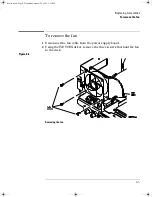
Page 94: ...e up as shown below 3 If a module is installed remove it from the oscilloscope 4 Using the T20 TORX driver remove the two screws from the rear of the cabinet 5 Using your thumbs gently push on the rear panel connectors to slide the oscilloscope out of the cabinet Figure 6 1 Removing the cabinet service book Page 4 Wednesday August 28 2002 3 25 PM ...

Page 95: ... fan To remove the fan 1 Disconnect the fan cable from the power supply board 2 Using the T20 TORX driver remove the three screws that hold the fan to the deck Figure 6 2 Removing the fan service book Page 5 Wednesday August 28 2002 3 25 PM ...

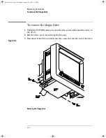
Page 96: ...ing the T8 TORX driver loosen the two screws that hold the drive to the deck 2 Lift the drive away from the system board 3 Disconnect the ribbon cable from the connector on the rear of the drive Figure 6 3 Removing the floppy drive service book Page 6 Wednesday August 28 2002 3 25 PM ...

Page 97: ...tions in Figure 6 4 Figure 6 4 Removing the intensity shaft and front panel 4 Swing the front panel out until the bottom clears the deck assembly then lift it up to free the hooks on top and pull it away from the deck When installing the front panel make sure that the power switch shaft is aligned with the connection hole in the front panel to make a proper connection Before engaging the retainer ...

Page 98: ...r removethefourscrewsthatholdthedisplay to the deck Set these screws aside Figure 6 5 Removing the display C A U T I O N USE CORRECT SCREWS TO AVOID SHORTING SYSTEM BOARD When you re install the display you must re insert the screws you removed in this step If you re insert screws that are longer they can short the system board to ground service book Page 8 Wednesday August 28 2002 3 25 PM ...

Page 99: ...switch After you disconnect the shaft make sure you position it in the recess along the side of the display bracket Figure 6 6 Unhooking the power switch shaft 5 Lift the display and remove it from the deck 6 When reinserting the power shaft push the shaft into the power switch until the shaft seats Gently apply outward pressure at this corner of the slot service book Page 9 Wednesday August 28 20...

Page 100: ...wo rear BNCs the 54641A and 54642A have one rear BNC 4 Using the T8 TORX driver remove two screws from module connector and remove the rear RFI gasket 5 Remove the intensity knob and shaft by grasping the knob with one hand and the grasping the shaft behind the front panel with the other hand and pulling the shaft straight out from the front panel 6 Disconnect the three ribbon cables and the calib...

Page 101: ...Assemblies To remove the system board 7 Lift the back of the board to clear the main deck and then pull the board straight out Figure 6 8 Removing the system board service book Page 11 Wednesday August 28 2002 3 25 PM ...

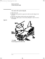
Page 102: ... the ground wire green wire with the yellow stripe from the deck 3 Disconnect the ribbon cable from the power supply board 4 Remove the printer power connector by sliding the connector out of the chassis Figure 6 9 Disconnecting ground wire and ribbon cable service book Page 12 Wednesday August 28 2002 3 25 PM ...

Page 103: ...ator shaft to the power switch then disconnect the shaft from the power switch After you disconnect the shaft make sure you position it in the recess along the side of the display bracket Figure 6 10 Unhooking the power switch shaft Gently apply outward pressure at this corner of the slot service book Page 13 Wednesday August 28 2002 3 25 PM ...

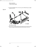
Page 104: ...ve the screw holding the power supply board to the deck Figure 6 11 Removing the power supply 7 Slide the power supply board toward the front panel about 1 2 inch Slip the power supply board keyhole slots off of the pins on the deck service book Page 14 Wednesday August 28 2002 3 25 PM ...

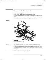
Page 105: ... of the small keyboard and simultaneously slide the small keyboard toward the main keyboard to remove Figure 6 12 Removing the keyboard assembly C A U T I O N USE CORRECT SCREWS TO AVOID DAMAGING FRONT PANEL LABEL When you re install the keyboard you must re insert the screws you removed in this step If you re insert screws that are longer they can damage the front panel label 5 Lift the keyboard ...

Page 106: ...handle Rotate the handle downward until it just passes the last detente position this is about 1 2 inch before the handle touches the bottom of the oscilloscope Pull the sides of the handle out of the cabinet service book Page 16 Wednesday August 28 2002 3 25 PM ...

Page 107: ...7 Replaceable Parts service book Page 1 Wednesday August 28 2002 3 25 PM ...

Page 108: ...gilent 54641A 42A Oscilloscope and Agilent 54641D 42D Mixed Signal Oscilloscope Diagrams and parts lists are included for assemblies and hardware that you can order Before working on the oscilloscope read the safety summary at the back of this book service book Page 2 Wednesday August 28 2002 3 25 PM ...

Page 109: ...logies can supply parts through a direct mail order system The advantages to the system are direct ordering and shipment from the Agilent Technologies Parts Center in Roseville California There is no maximum or minimum on any mail order There is a minimum amount for parts ordered through a local Agilent Technologies Sales Office when the orders require billing and invoicing Transportation costs ar...

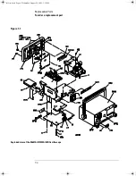
Page 110: ...7 4 Replaceable Parts To order a replacement part Figure 7 1 Exploded view of the 54641A 41D 42A 42D Oscilloscope service book Page 4 Wednesday August 28 2002 3 25 PM ...

Page 111: ...1 1 Fuse 6 3 A 250 V SB A5 2090 0384 1 Display Assembly A6 54622 66502 1 Keyboard 2 CH 54641A 42A A6 54622 66503 1 Keyboard 2 16 CH MSO 54641D 42D B1 3160 1006 1 Fan H1 0515 0372 5 T 10 Machine Screw H2 0515 0380 6 T 20 Machine Screw 4 x 0 7 x 10mm H3 0515 0390 4 T 20 Machine Screw 4 x 0 7 x 6mm H4 0515 0658 2 T 6 Pan Head Machine Screw H5 0515 0667 3 T 10 Machine Screw 3 x 0 5 x 25mm H6 0515 1410...

Page 112: ...ront Panel Label Set 54642D MP17 54642 94303 1 Power Specification Rear Cabinet Label MP18 54642 64401 1 Cabinet Assembly with handle and feet installed MP19 54642 09105 1 Ground Spring from Power Supply to Deck MP20 54642 60600 1 RFI Shield Keyboard MP21 54642 60601 1 RFI Shield Chassis Side MP22 8160 0824 1 Ground Spring on Bottom of Deck MP23 54622 44901 1 Handle part of MP18 W1 54630 61601 1 D...

Page 113: ...r 54600 68722 5041 9482 Pouch 54601 44101 Front panel cover Probes 10073C 2 10 1 500 MHz passive probe with ID Input Cable 54641D 42D only 54620 61801 1 Cable Woven includes probe leads 5959 9333 Package replacement probe leads quantity 5 5959 9334 Package replacement probe grounds quantity 5 5959 9335 Package replacement pod grounds quantity 5 5090 4833 Package replacement grabber quantity 20 016...

Page 114: ...7 8 service book Page 8 Wednesday August 28 2002 3 25 PM ...
Page 115: ... 4 4 1995 0 5 kV signal lines 1 kV power lines IEC 61000 4 5 1995 EN 61000 4 5 1995 0 5 kv line line 1 kV line ground IEC 61000 4 6 1996 EN 61000 4 6 1996 3V 0 15 80 MHz IEC 61000 4 11 1994 EN 61000 4 11 1994 1 cycle 100 Canada ICES 001 1998 Australia New Zealand AS NZS 2064 1 Safety IEC 61010 1 1990 A1 1992 A2 1995 EN 61010 1 1993 A2 1995 Canada CSA C22 2 No 1010 1 1992 The product herewith compl...

Page 116: ...A C22 2 No 1010 1 1992 USA UL 3111 1 1994 optional Additional Information The product herewith complies with the requirements of the Low Voltage Directive 73 23 EEC and the EMC Directive 89 336 EEC including 93 68 EEC and carries the CE Marking accordingly European Union 1 Performance Criteria A Pass Normal operation no effect B Pass Temporary degradation self recoverable C Pass Temporary degradat...

Page 117: ... 4 4 1995 0 5 kV signal lines 1 kV power lines IEC 61000 4 5 1995 EN 61000 4 5 1995 0 5 kv line line 1 kV line ground IEC 61000 4 6 1996 EN 61000 4 6 1996 3V 0 15 80 MHz IEC 61000 4 11 1994 EN 61000 4 11 1994 1 cycle 100 Canada ICES 001 1998 Australia New Zealand AS NZS 2064 1 Safety IEC 61010 1 1990 A1 1992 A2 1995 EN 61010 1 1993 A2 1995 Canada CSA C22 2 No 1010 1 1992 The product herewith compl...

Page 118: ...A C22 2 No 1010 1 1992 USA UL 3111 1 1994 optional Additional Information The product herewith complies with the requirements of the Low Voltage Directive 73 23 EEC and the EMC Directive 89 336 EEC including 93 68 EEC and carries the CE Marking accordingly European Union 1 Performance Criteria A Pass Normal operation no effect B Pass Temporary degradation self recoverable C Pass Temporary degradat...

Page 119: ... 4 4 1995 0 5 kV signal lines 1 kV power lines IEC 61000 4 5 1995 EN 61000 4 5 1995 0 5 kv line line 1 kV line ground IEC 61000 4 6 1996 EN 61000 4 6 1996 3V 0 15 80 MHz IEC 61000 4 11 1994 EN 61000 4 11 1994 1 cycle 100 Canada ICES 001 1998 Australia New Zealand AS NZS 2064 1 Safety IEC 61010 1 1990 A1 1992 A2 1995 EN 61010 1 1993 A2 1995 Canada CSA C22 2 No 1010 1 1992 The product herewith compl...

Page 120: ...A C22 2 No 1010 1 1992 USA UL 3111 1 1994 optional Additional Information The product herewith complies with the requirements of the Low Voltage Directive 73 23 EEC and the EMC Directive 89 336 EEC including 93 68 EEC and carries the CE Marking accordingly European Union 1 Performance Criteria A Pass Normal operation no effect B Pass Temporary degradation self recoverable C Pass Temporary degradat...

Page 121: ...4 4 1995 0 5 kV signal lines 1 kV power lines IEC 61000 4 6 1996 EN 61000 4 6 1996 3 V 0 15 80 MHz Canada ICES 001 1998 Australia New Zealand AS NZS 2064 1 Safety IEC 61010 1 1990 A1 1992 A2 1995 EN 61010 1 1993 A2 1995 Canada CSA C22 2 No 1010 1 1992 Additional Information The product herewith complies with the requirements of the Low Voltage Directive 73 23 EEC and the EMC Directive 89 336 EEC i...

Page 122: ...ements of the Low Voltage Directive 73 23 EEC and the EMC Directive 89 336 EEC including 93 68 EEC and carries the CE Marking accordingly European Union 1 Performance Criteria A Pass Normal operation no effect B Pass Temporary degradation self recoverable C Pass Temporary degradation operator intervention required D Fail Not recoverable component damage Sound Pressure Level Less than 60 dBA Regula...

Page 123: ...ed to the earth termi nal of the power source Whenever it is likely that the ground protection is impaired you must make the instrument inoperative and secure it against any unintended operation Service instructions are for trained service personnel To avoid dangerous electric shock do not perform any service unless qualified to do so Do not attempt internal service or adjustment unless another pe...

Page 124: ...d without notice in future editions Further to the maximum extent permitted by applica ble law Agilent disclaims all warranties either express or implied with regard to this manual and any information contained herein including but not limited to the implied war ranties of merchantability and fitness for a particular purpose Agilent shall not be liable for errors or for inci dental or consequentia...

Reviews: