6- 8
Replacing Assemblies
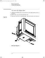
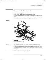
To remove the display
To remove the display
1
Remove the front panel from the oscilloscope.
2
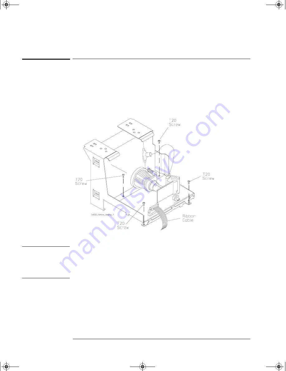
Disconnect the ribbon cable from the display board.
3
Using the T20 TORX driver, remove the four screws that hold the display
to the deck. Set these screws aside.
Figure 6-5
Removing the display
C A U T I O N
USE CORRECT SCREWS TO AVOID SHORTING SYSTEM BOARD !
When you re-install the display, you must re-insert the screws you removed in
this step. If you re-insert screws that are longer, they can short the system
board to ground.
service.book Page 8 Wednesday, August 28, 2002 3:25 PM
Summary of Contents for 54641A
Page 4: ...iv service book Page iv Wednesday August 28 2002 3 25 PM ...
Page 7: ...1 General Information ...
Page 24: ...1 18 ...
Page 25: ...2 Preparing the Oscilloscope for Use service book Page 1 Wednesday August 28 2002 3 25 PM ...
Page 45: ...3 Testing Performance service book Page 1 Wednesday August 28 2002 3 25 PM ...
Page 66: ...3 22 service book Page 22 Wednesday August 28 2002 3 25 PM ...
Page 67: ...4 Calibrating and Adjusting service book Page 1 Wednesday August 28 2002 3 25 PM ...
Page 76: ...4 10 service book Page 10 Wednesday August 28 2002 3 25 PM ...
Page 77: ...5 Troubleshooting service book Page 1 Wednesday August 28 2002 3 25 PM ...
Page 90: ...5 14 service book Page 14 Wednesday August 28 2002 3 25 PM ...
Page 91: ...6 Replacing Assemblies service book Page 1 Wednesday August 28 2002 3 25 PM ...
Page 107: ...7 Replaceable Parts service book Page 1 Wednesday August 28 2002 3 25 PM ...
Page 114: ...7 8 service book Page 8 Wednesday August 28 2002 3 25 PM ...

