background image

FINAL

TRIM

SIZE

:

7.5

in

x

9.0

in

Certication

Agilent

T

echnologies

certies

that

this

product

met

its

published

specications

at

the

time

of

shipment

from

the

factory

.

Agilent

T

echnologies

further

certies

that

its

calibration

measurements

are

traceable

to

the

United

States

National

Institute

of

Standards

and

T

echnology

,

to

the

extent

allowed

by

the

Institute's

calibration

facility

,

and

to

the

calibration

facilities

of

other

International

Standards

Organization

members

.

iii

Summary of Contents for 54751A

Page 1: ......

Page 2: ...FINAL TRIM SIZE 7 5 in x 9 0 in User s Guide Agilent 83483A 4A 4B and 54751A 2A 2B Plug In Modules ...

Page 3: ...cidental or consequential damages in connection with the furnishing performance or use of this material Restricted Rights Legend Use duplication or disclosure by the U S Government is subject to restrictions as set forth in subparagraph c 1 ii of the Rights in Technical Data and Computer Software clause at DFARS 252 227 7013 for DOD agencies and subparagraphs c 1 and c 2 of the Commercial Computer...

Page 4: ... of shipment from the factory Agilent Technologies further certi es that its calibration measurements are traceable to the United States National Institute of Standards and Technology to the extent allowed by the Institute s calibration facility and to the calibration facilities of other International Standards Organization members iii ...

Page 5: ...hnologies for use with an instrument will execute its programming instructions when properly installed on that instrument Agilent Technologies does not warrant that the operation of the instrument or software or rmware will be uninterrupted or error free Limitation of Warranty The foregoing warranty shall not apply to defects resulting from improper or inadequate maintenance by Buyer Buyer supplie...

Page 6: ...o obtain servicing information or to order replacement parts contact the nearest Agilent Technologies Sales and Service O ce In any correspondence or telephone conversation refer to the instrument by its model number serial number and option designation Before returning an instrument for service call the Agilent Technologies Instrument Support Center at 800 403 0801 visit the Test and Measurement ...

Page 7: ... 358 10 855 2360 France 01 69 82 66 66 Germany 0180 524 6330 India 080 34 35788 Italy 39 02 9212 2701 Ireland 01 615 8222 Japan 81 426 56 7832 Korea 82 2 3770 0419 Mexico 5 258 4826 Netherlands 020 547 6463 Norway 22 73 57 59 Russia 7 095 797 3930 Spain 34 91 631 1213 Sweden 08 5064 8700 Switzerland 01 735 7200 United Kingdom 01 344 366666 United States and Canada 800 403 0801 vi ...

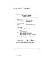
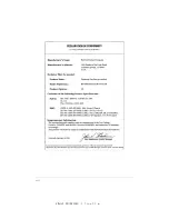
Page 8: ...FINAL TRIM SIZE 7 5 in x 9 0 in Declaration of Conformity vii ...

Page 9: ...FINAL TRIM SIZE 7 5 in x 9 0 in viii ...

Page 10: ... destruction of the instrument Do not proceed beyond a caution sign until the indicated conditions are fully understood and met WAR NING The warning sign denotes a life threatening hazard It calls attention to a procedure which if not correctly performed or adhered to could result in injury or loss of life Do not proceed beyond a warning sign until the indicated conditions are fully understood and...

Page 11: ...personnel WA RNING If this instrument is not used as speci ed the protection provided by the equipment could be impaired This instrument must be used in a normal condition in which all means for protection are intact only CA UTION Before this instrument is switched on make sure its primary power circuitry has been adapted to the voltage of the ac power source Failure to set the ac power input to t...

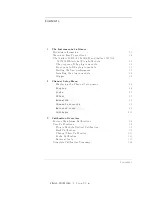
Page 12: ... 2 4 NNNNNNNNNNNNNNNNNNNNNNN Display 2 4 NNNNNNNNNNNNNNNNN Scale 2 5 NNNNNNNNNNNNNNNNNNNN Offset 2 5 NNNNNNNNNNNNNNNNNNNNNNNNNNNNNNNNNNNNNNNNNNNN Bandwidth 2 6 NNNNNNNNNNNNNNNNNNNNNNNNNNNNNNNNNNNNNNNNNNNNNNNNNNNNN Channel autoscale 2 6 NNNNNNNNNNNNNNNNNNNNNNNNNNNNNNNNNNNNNNNNNNNNNNNNNNNNNNNNNNNNNN External scale 2 7 NNNNNNNNNNNNNNNNNNNNNNNNNNNNN Calibrate 2 10 3 Calibration Overview Factory Mainfr...

Page 13: ...5 in x 9 0 in 4 Speci cations and Characteristics Speci cations 4 3 Characteristics 4 8 5 In Case of Di culty If the mainframe does not operate 5 3 If the plug in does not operate 5 4 Error Messages 5 6 Index Contents 2 ...

Page 14: ... display 2 11 3 1 Current Frame 1Temp condition 3 5 3 2 Dark calibration menu 3 9 3 3 Electrical Channel Calibrate Menu 3 12 3 4 External Scale Menu 3 13 T ables 3 1 Factory Calibration Summary 3 4 3 2 Electrical Channel User Calibration Summary 3 6 3 3 Miscellaneous User Calibration Summary 3 7 3 4 Complete Calibration Summary 3 14 Contents 3 ...

Page 15: ...FINAL TRIM SIZE 7 5 in x 9 0 in Contents ...

Page 16: ...FINAL TRIM SIZE 7 5 in x 9 0 in 1 The Instrument at a Glance ...

Page 17: ...ching the front panel input connectors without rst touching the frame of the instrument Be sure the instrument is properly earth grounded to prevent buildup of static charge The electrical plug in module provides two accurate measurement channels with user selectable bandwidths The lower bandwidth mode provides excellent oscilloscope noise performance for accurate measurement of small signals The ...

Page 18: ...ntation Option 0B0 Deletes the user documentation Option UK6 Measured performance data Optionalaccessories Agilent 54006A 6 GHz divider probe Agilent 54008A 22 ns delay line Agilent 54118A 500 MHz to 18 GHz trigger Agilent 10086A ECL terminator SMA f f adapter Agilent part number 1250 1158 APC 2 4 f f adapter Agilent 11900B APC 3 5 f f adapter Agilent part number 1250 1749 1 3 ...

Page 19: ... which menu is selected Shifted functions are indicated by the front panel 4Shift5 key followed by the shaded shifted function for example the Local function above the 4Stop Single5 front panel key will be shown as 4Shift5 4Local5 A softkey with On and O in its label can be used to turn the softkey s function on or o To turn the function on press the softkey so On is highlighted To turn the functi...

Page 20: ...FINAL TRIM SIZE 7 5 in x 9 0 in The Instrument at a Glance MenuandKeyConventions value use the general purpose knob located below the front panel Measure section 1 5 ...

Page 21: ... a trigger signal input to the time base trigger board inside the mainframe Front panel of the plug in module The plug in module takes up two of the four mainframe slots The front panel of the plug in module has two channel inputs and an external trigger input The front panel also has two Probe Power connectors for Agilent 54700 series probes an Aux Power connector for general purpose use and a ke...

Page 22: ......

Page 23: ... loaded so nger tighten the knurled screw on the front panel of the plug in module to make sure the plug in is securely seated in the mainframe CA UTION Do not use extender cables to operate the plug in module outside of the mainframe The plug in module using extender cables can be damaged by improper grounding when using extender cables Trigger The external trigger level range for this plug in mo...

Page 24: ...c discharges to the front panel input connectors Before connecting any coaxial cable to the connectors momentarily short the center and outer conductors of the cable together Avoid touching the front panel input connectors without rst touching the frame of the instrument Be sure the instrument is properly earth grounded to prevent buildup of static charge 1 9 ...

Page 25: ...FINAL TRIM SIZE 7 5 in x 9 0 in TheInstrumentata Glance ...

Page 26: ...FINAL TRIM SIZE 7 5 in x 9 0 in 2 Channel Setup Menu ...

Page 27: ...ductors of the cable together Avoid touching the front panel input connectors without rst touching the frame of the instrument Be sure the instrument is properly earth grounded to prevent buildup of static charge At the top of the plug in module are the 4Channel5 keys These keys give you access to the Channel Setup menu for each input The Channel Setup menu is displayed on the right side of the sc...

Page 28: ...FINAL TRIM SIZE 7 5 in x 9 0 in ChannelSetupMenu Figure2 1 ElectricalChannel Setupmenu 2 3 ...

Page 29: ...the channel is turned o or an automatic measurement is performed The automatic measurement results share the same area of the display as the channel setups When the channel display is o the waveform display for that channel is turned o pulse parameter measurements are stopped and acquisition on that channel is stopped unless it is needed as an operand for waveform math functions Even though the ch...

Page 30: ...aaaaaaaaaaaa Offset The O set softkey moves the waveform vertically It is similar to the position control on analog oscilloscopes The advantage of digital o set is that it is calibrated The o set voltage is the voltage at the center of the graticule area and the range of o set is 500 mV You can use the knob arrow keys or keypad to change the o set setting The ne mode also works with o set When an ...

Page 31: ...dwidth aaaaaaaaaaaaaaaaaaaaaaaaaaaaaaaaaaaaaaaaaaaaaaaaaaaaaaaaaaaaaaaaaaaaaaaaaaaaaaaaaaa Channel autoscale The Channel Autoscale function provides a convenient and fast method for determining the standard vertical scale setting with the highest resolution that will not clip the waveform Timebase and trigger settings are not a ected This function is useful in manufacturing environments where the ...

Page 32: ...rical converters or attenuators Scaling is automatically adjusted to account for the external device KeyPath 4Channel5 NNNNNNNNNNNNNNNNNNNNNNNNNNNNNNNNNNNNNNNNNNNNNNNNNNNNNNNNNNNNNN External scale NNNNNNNNNNNNNNNNNNNNNNNNNNNNNNNNNNN Atten units The Atten Units function lets you select how you want the probe attenuation factor represented The choices are either decibel or ratio The formula for calc...

Page 33: ...ctual signal at the input to the external device The attenuation range is from 0 0001 1 to 1 000 000 1 When you connect a compatible active probe to the probe power connector adjacent to the corresponding channel input the instrument automatically sets the attenuation For all other devices set the probe attenuation with the knob arrow keys or keypad NOT E Refer to Chapter 3 for information on cali...

Page 34: ...tional functions allow you to compensate for the actual characteristics of the probe rather than its ideal characteristics For example you might have an ampli ed lightwave converter with ideal characteristics of 300 V W with 0 V o set But its actual characteristics are 324 V W with 1 mV of output o set Therefore set the External Gain to 324 V W and the External O set to 1 mV KeyPath 4Channel5 NNNN...

Page 35: ...gered edge at the center of the display when you are using a power splitter connected between the channel and trigger inputs Another use for skew is when you are comparing two waveforms that have a timing di erence between them If you are more interested in comparing the shapes of two waveforms rather than the actual timing di erence between them you can use Skew to overlay one waveform on top of ...

Page 36: ... Date This is the current date and time You can compare this to the last plug in module calibration time That way you will know how long it has been since the last plug in module calibration was performed Current Frame 1Temp This is the temperature change on the inside of the instrument since the last mainframe calibration was performed A positive number indicates how many degrees warmer the mainf...

Page 37: ...re 1 is the temperature change from the temperature of the mainframe when the last calibration was performed If this temperature 1 is greater than 65 C since the last mainframe calibration then you must perform a plug in module calibration to achieve the speci ed dc accuracy NNNNNNNNNNNNNNNNNNNNNNNNNNNNNNNNNNNNNNNNNNNNNNN Calibrate probe Connect a voltage probe to the plug in and then press NNNNNN...

Page 38: ...FINAL TRIM SIZE 7 5 in x 9 0 in 3 Calibration Overview ...

Page 39: ...y calibrations A factory calibration consists of verifying instrument performance to all speci cations If an instrument fails to meet speci cations adjustment or repair may be necessary For most users this will mean shipping the instrument back to an authorized service center Some users may purchase the required instrumentation and perform the factory timebase calibrations themselves using the opt...

Page 40: ...ormed on a periodic basis Agilent designs instruments to meet speci cations over the recommended calibration interval provided that the instrument is operated within the speci ed operating environment To maintain speci cations periodic recalibrations are necessary We recommend that the plug in module be calibrated at an Agilent Technologies service facility every 12 months Users are encouraged to ...

Page 41: ...time base measurements such as rise time fall time eye width and jitter Annually at Agilent Technologies service center or if operating temp has changed and remains 5 C or more from calibration temperature See service manual 4Utility5 FFFFFFFFFFFFFFFFFFFFFFFFFF Calibrate FFFFFFFFFFFFFFFFFFFFFFFFFFFFFFFFFFFFFFFFFFF Calibrate frame CA UTION To prevent access to the mainframe calibration switch place...

Page 42: ... the display as shown in the following gure Figure3 1 CurrentFrame 1Tempcondition If the Current Frame 1Temp listing is greater than 65 C then the mainframe should either be calibrated at the current operating temperature or be placed in an ambient air temperature that is within 5 C of the temperature of the current calibration 3 5 ...

Page 43: ...and are strongly recommended Table 3 2 ElectricalChannelUser CalibrationSummary Calibration What is calibrated Measurements A ected Recommended Interval Key Path Plug in Vertical Calibration Vertical o set and vertical scale accuracy Any electrical vertical measurements such as Vp to p eye height extinction ratio Perform after any power cycle or once every 10 hours during continuous use or if oper...

Page 44: ...sates for gain or loss associated with external devices calibrates vertical scale to external device Any measurement taken through an external device component or transducer Whenever using external devices component or transducer 4Channel Setup5 FFFFFFFFFFFFFFFFFFFFFFFFFFFFFFFFFFFFFFFFFFF External Scale Plug in Module V ertical Calibration The plug in module vertical calibration allows the instrum...

Page 45: ...e signals are both generated and routed internally 1 Remove any front panel connections from electrical channels 2 Press 4Utility5 NNNNNNNNNNNNNNNNNNNNNNNNNNNNNNNNNNNNNNNNNNNN Calibrate and then NNNNNNNNNNNNNNNNNNNNNNNNNNNNNNNNNNNNNNNNNNNNNNNNNNNNNNNNNNNNNNNNNNNN Calibrate plug in 3 Select the plug in module to be calibrated press NNNNNNNNNNNNNNNNNNNNNNN 1 and 2 or NNNNNNNNNNNNNNNNNNNNNNN 3 and 4 ...

Page 46: ...NNNNNNNNNNNNNNNNNN Color grade softkey and set its setting to NNNNNNNN on Color grade must be enabled to perform an extinction ratio measurement and a Dark calibration In addition the dark level amplitude when there is no signal present must be on the screen to perform a Dark calibration 2 Press the blue shift key and then the NNNNNNNNNNNNNNNNNNNNNNNNNN Meas eye softkey which is located beneath th...

Page 47: ...els on and overlay the signals vertically 2 Expand the time base so that the rising edges are at about a 45 angle 3 Press the plug in module s front panel channel 4SETUP5 key 4 Press NNNNNNNNNNNNNNNNNNNNNNNNNNNNN Calibrate and then NNNNNNNNNNNNNN Skew 5 Adjust the skew on one of the channels so that the rising edges overlap at the 50 points Probe Calibration For active probes such as the Agilent 5...

Page 48: ...NNNNNNNNNNNNNNNNNNNNNNNNNNNN Attenuation You can use the probe calibration to calibrate any network including probes or cable assemblies The instrument calibrates the voltage at the tip of the probe or the cable input Tocalibrate anAgilent identi ableprobe 1 Press the plug in module s front panel channel 4SETUP5 key 2 Press NNNNNNNNNNNNNNNNNNNNNNNNNNNNN Calibrate and then NNNNNNNNNNNNNNNNNNNNNNNNN...

Page 49: ...he actual characteristics you can refer to the typical speci cations that came with the probe or device 1 Press the plug in module s front panel channel 4SETUP5 key 2 Press NNNNNNNNNNNNNNNNNNNNNNNNNNNNNNNNNNNNNNNNNNNN External scale 3 Press NNNNNNNNNNNNNNNNNNNNNNNNNNNNNNNNNNN Atten units Ratio NNNNNNNNNNNNNNNNNNNNNNNNNNNNNNNNNNN Attenuation 1 1 and then NNNNNNNNNNNNNNNNN Units Ampere Volt Watt or ...

Page 50: ...vices such as test xtures and attenuators so that the reading on the display gives the measurement value associated with only the actual device under test Toadjust theexternal scale 1 Press the plug in module s front panel channel 4SETUP5 key 2 Press NNNNNNNNNNNNNNNNNNNNNNNNNNNNNNNNNNNNNNNNNNNN External scale and set the NNNNNNNNNNNNNNNNNNNNNNNNNNNNNNNNNNN Atten units to decibel 3 Press NNNNNNNNNN...

Page 51: ... used in the extinction ratio algorithm Channels a ected electrical with O E converter Extinction ratio Before extinction ratio measurements if the vertical scale or o set has changed since the last dark calibration or after a plug in vertical calibration is performed 4Shift5 4Meas eye5 FFFFFFFFFFFFFFFFFFFFFFFFFFFFFFFFFFFFFFFFFFFFFF Extinction ratio FFFFFFFFFFFFFFFFFFFFFFFF Dark Cal Probe calibrat...

Page 52: ...FINAL TRIM SIZE 7 5 in x 9 0 in 4 Speci cations and Characteristics ...

Page 53: ...ed performance Unless otherwise noted corrected limits are given when speci cations are subject to minimization with error correction routines Characteristics Characteristics provide useful nonwarranted information about the functions and performance of the instrument Characteristics are printed in italics Calibrationcycle Agilent Technologies designs instruments to meet speci cations over the rec...

Page 54: ...wing are speci cations used to test the Agilent 83483A 83484A B and the Agilent 54751A 54752A B plug in modules Speci cations are valid after a 1 hour warm up period Refer to the Agilent 54701A Active Probe Service Guide for complete probe speci cations 4 3 ...

Page 55: ... 2 C 1Tcal 2 reading 0 0 4 hr 1Time3 reading Transition Time 10 90 characteristic calculated from T 0 35 BW electrical 12 4 GHz bandwidth 28 2 ps 20 GHz bandwidth 17 5 ps RMS Noise Typical 12 4 GHz 0 25 mV 20 GHz 0 5 mV Maximum 12 4 GHz 0 5 mV 20 GHz 1 0 mV 1 It is recommended that a user vertical calibration be performed after every 10 hours of continuous use or if the temperature has changed by ...

Page 56: ...actor full scale is eight divisions Minimum 1 mV div Maximum 100 mV div dc O set Range 6500 mV Nominal Input Impedance 50 Connectors 3 5mm m channel and trigger Input Re ection Return Loss 5 for 30 ps rise time Number of Channels 2 Dynamic Range Maximum Speci ed Input Power 6400 mV relative to channel o set Maximum Safe Input 62V peak ac 16 dBm 4 5 ...

Page 57: ... of delta reading 6 2 C 1Tcal delta reading 2 Transition Time 10 90 characteristic calculated from T 0 35 BW electrical 26 5 GHz bandwidth 13 2 ps 50 GHz bandwidth 7 0 ps RMS Noise Typical 26 5 GHz 0 46 mV 50 GHz 0 92 mV Maximum 26 5 GHz 0 75 mV 50 GHz 1 5 mV Scale Factor full scale is eight divisions Minimum 1 mV div Maximum 100 mV div dc O set Range 6500 mV Nominal Input Impedance 50 1 It is rec...

Page 58: ...2 Dynamic Range Maximum Speci ed Input Power 6400 mV relative to channel o set Maximum Safe Input 62V peak ac 16 dBm Environmentalspeci cations Temperature Operating 15 C to 35 C Non operating 040 C to 70 C Humidity Operating up to 90 relative humidity non condensing at 35 C Non operating up to 95 relative humidity non condensing at 65 C Powerrequirements Supplied by mainframe Weight Net approxima...

Page 59: ...lug in module See the Agilent 54701A Active Probe Service Guide for complete probe characteristics TriggerInput Characteristics Nominal Impedance 50 Input Connector 3 5 mm m Trigger Level Range 61 V Maximum Safe Input Voltage 62 Vdc ac peak 16 dBm Percent Re ection 10 for 100 ps rise time Refer to the Agilent 83480A 54750A User s Guide for Trigger speci cations 4 8 ...

Page 60: ......

Page 61: ... ESD on or near input connectors can damage circuits inside the instrument Repair of damage due to misuse is not covered under warranty Before connecting any cable to the electrical input momentarily short the center and outer conductors of the cable together Personnel should be properly grounded and should touch the frame of the instrument before touching any connector Review the procedure being ...

Page 62: ...es the line socket have power Is the unit plugged in to the proper ac power source Is the mainframe turned on Is the rear panel line switch set to on Will the mainframe power up without the plug in module installed If the mainframe still does not power up refer to the optional Agilent 83480A 54750A Service Guide or return the mainframe to a quali ed service department 5 3 ...

Page 63: ...cquire data by pressing NNNNNNNNNNN Run Find any signals on the channel inputs by pressing 4Autoscale5 See if any signals are present at the channel inputs by pressing 4Trigger5 NNNNNNNNNNNNNNNNN Sweep NNNNNNNNNNNNNNNNNNNNNNN freerun After viewing the signal press NNNNNNNNNNNNNNNNNNNNNNNNNNNNN triggered Make sure Channel Display is on by pressing 4Channel5 NNNNNNNNNNNNNNNNNNNNNNNNNNNNNNNNNNNNNNNNN...

Page 64: ...n Agilent 83485A or other optical module It will destroy the factory optical electrical calibration factors a To reinitialize the plug in memory press 4Utility5 NNNNNNNNNNNNNNNNNNNNNNN Service NNNNNNNNNNNNNNNNNNNNNNNNNNNNNNNNNNNNNNNNN Plug in b Select the appropriate plug in by selecting slot 1 and 2 or 3 and 4 by pressing NNNNNNNNNNNNNNNNNNNNNNN Plug in 1 or 3 NNNNNNNNNNNNNNNNNNNNNNNNNNNNNNNNNNNN...

Page 65: ...uide for the mainframe Memoryerror occurred inplug in Try reinstallingplug in The mainframe could not correctly read the contents of the memory in the plug in 1 Remove and reinstall the plug in module Each time a plug in is installed the mainframe rereads the plug in module s memory 2 Verify the plug in module is rmly seated in the mainframe slot 3 Verify the knurled screws at the bottom of the pl...

Page 66: ...o the optional Agilent 83483A 54751A Service Guide or Agilent 83484A B and 54752A B Service Guide IDerroroccurred in plug in Serviceis required The information read from the plug in module s memory does not match the hardware in the plug in module This can be caused by a communication problem between the mainframe and the plug in module Make sure there is a good connection between the mainframe an...

Page 67: ...FINAL TRIM SIZE 7 5 in x 9 0 in InCaseofDi culty ...

Page 68: ...FINAL TRIM SIZE 7 5 in x 9 0 in Index ...

Page 69: ... 2 7 automatic measurement 2 4 auxiliary power connector 1 6 B Bandwidth softkey 2 6 C Calibrate probe softkey 2 12 Calibrate softkey 2 10 calibration external scale 3 10 factory 3 4 mainframe 3 4 O E converters 3 10 overview 3 2 plug in module vertical calibration 3 7 probe 3 10 probes 3 10 skew 3 10 status 5 4 user 3 6 validity 2 12 vertical 1 7 voltage probe 3 10 CAL signal 2 12 Cal status soft...

Page 70: ... of conformity vii declaration of conformity vii description of the plug in module 1 2 digital o set 2 5 Display softkey 2 4 E environmental speci cations 4 7 error messages 5 6 7 extender cables 1 8 external scale calibration 3 10 External scale softkey 2 7 external trigger input 1 6 level 1 8 Ext gain softkey 2 9 Ext o set softkey 2 9 F factory calibration 3 4 front panel overview 1 6 H horizont...

Page 71: ...s 1 3 ordering information 1 3 P plug in characteristics 4 8 Plug in message 2 12 plug in module description 1 2 features 1 6 front panel 1 6 installation 1 8 power requirements 4 7 purpose 1 6 speci cations 4 3 7 troubleshooting 5 4 weight 4 7 plug in module vertical calibration 3 7 power level 2 5 power requirements 4 7 probe attenuation 2 8 2 12 attenuation factor 2 7 characteristics 2 9 power ...

Page 72: ...e change 2 11 12 trigger external 1 8 input characteristics 4 8 level 2 9 source 2 4 troubleshooting 5 7 typeface conventions 1 1 U Units softkey 2 5 2 9 user calibrations 3 6 V vertical calibration 1 7 measurement 2 9 scale 2 4 5 2 6 speci cations 4 3 4 5 waveform 2 5 voltage measurement 2 8 probe 2 12 voltage probe calibration 3 10 W warranty information iv wattage measurement 2 8 waveform displ...

Page 73: ...FINAL TRIM SIZE 7 5 in x 9 0 in ...

Reviews: