FINAL
TRIM
SIZE
:
7.5
in
x
9.0
in
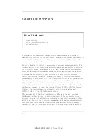
Calibration
Overview
User
Calibrations
T
able
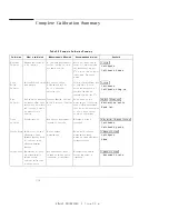
3-3.
Miscellaneous
User
Calibration
Summary
Calibration
What
is
calibrated
Measurements
Aected
Recommended
Interval
K
ey
Path
Probe
calibration
Probe
Attenuation
An
y
electrical
measurement
taken
with
the
probe
Whenever
a
probe
is
connected
4
Electrical
Channel
Setup
5
FFFFFFFFFFFFFFFFFFFFFFFFFF
Calibrate
FFFFFFFFFFFFFFFFFFFFFFFFFFFFFFFFFFFFFFFFFFF
Calibrate
probe
Channel
Skew
Calibrates
out
the
small
dierences
in
dela
y
between
channels.
Useful
for
looking
at
timing
dierences
between
channels
Multiple
channel
measurements
Before
multiple
channel
measurements
when
measuring
timing
dierences
between
channels.
4
Channel
Setup
5
FFFFFFFFFFFFFFFFFFFFFFFFFF
Calibrate
FFFFFFFFFFFFF
Skew
External
Scale
Compensates
for
gain
or
loss
associated
with
external
devices
(calibrates
vertical
scale
to
external
device)
An
y
measurement
taken
through
an
external
device
(component
or
transducer)
Whenever
using
external
devices
(component
or
transducer)
4
Channel
Setup
5
FFFFFFFFFFFFFFFFFFFFFFFFFFFFFFFFFFFFFFFFFFF
External
Scale
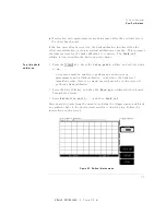
Plug-in
Module
V
ertical
Calibration
The
plug-in
module
vertical
calibration
allows
the
instrument
to
establish
the
calibration
factors
for
a
specic
plug-in
when
the
plug-in
is
installed
in
the
mainframe
.
The
plug-in
calibration
factors
are
valid
only
for
the
specic
mainframe
slot
in
which
it
was
calibrated.
The
plug-in
vertical
calibration
establishes
vertical
accuracy
.
A
plug-in
vertical
calibration
should
be
done
if:
The
mainframe
has
cycled
power
.
The
plug-in
has
been
repaired,
reprogrammed,
or
removed
from
the
mainframe
.
The
instrument's
operating
temperature
has
changed
and
remains
more
than
5
C
from
the
temperature
at
which
the
Plug-in
calibration
was
performed.
3-7
Summary of Contents for 54751A
Page 1: ......
Page 8: ...FINAL TRIM SIZE 7 5 in x 9 0 in Declaration of Conformity vii ...
Page 9: ...FINAL TRIM SIZE 7 5 in x 9 0 in viii ...
Page 15: ...FINAL TRIM SIZE 7 5 in x 9 0 in Contents ...
Page 16: ...FINAL TRIM SIZE 7 5 in x 9 0 in 1 The Instrument at a Glance ...
Page 22: ......
Page 25: ...FINAL TRIM SIZE 7 5 in x 9 0 in TheInstrumentata Glance ...
Page 26: ...FINAL TRIM SIZE 7 5 in x 9 0 in 2 Channel Setup Menu ...
Page 28: ...FINAL TRIM SIZE 7 5 in x 9 0 in ChannelSetupMenu Figure2 1 ElectricalChannel Setupmenu 2 3 ...
Page 38: ...FINAL TRIM SIZE 7 5 in x 9 0 in 3 Calibration Overview ...
Page 52: ...FINAL TRIM SIZE 7 5 in x 9 0 in 4 Speci cations and Characteristics ...
Page 60: ......
Page 67: ...FINAL TRIM SIZE 7 5 in x 9 0 in InCaseofDi culty ...

