FINAL
TRIM
SIZE
:
7.5
in
x
9.0
in
Calibration
Overview
User
Calibrations
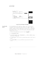
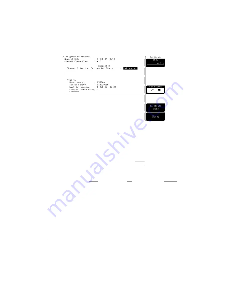
Figure
3-3.
Electrical
Channel
Calibrate
Menu
T
o
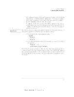
calibrate
other
devices
Since
the
mainframe's
CAL
signal
is
a
voltage
source
,
it
cannot
be
used
to
calibrate
to
the
probe
tip
when
the
units
are
set
to
Ampere
,
W
att,
or
Unknown.
Instead,
set
the
external
gain
and
external
oset
to
compensate
for
the
actual
characteristics
of
the
probe
or
device
.
If
you
do
not
know
the
actual
characteristics
,
you
can
refer
to
the
typical
specications
that
came
with
the
probe
or
device
.
1.
Press
the
plug-in
module's
front-panel
channel
4
SETUP
5
key
.
2.
Press
NNNNNNNNNNNNNNNNNNNNNNNNNNNNNNNNNNNNNNNNNNNN
External
scale
.
3.
Press
NNNNNNNNNNNNNNNNNNNNNNNNNNNNNNNNNNN
Atten
units
Ratio
,
NNNNNNNNNNNNNNNNNNNNNNNNNNNNNNNNNNN
Attenuation
1:1,
and
then
NNNNNNNNNNNNNNNNN
Units
Ampere
(V
olt,
W
att,
or
Unknown).
4.
Press
NNNNNNNNNNNNNNNNNNNNNNNNNN
Ext
gain
,
and
enter
the
actual
gain
characteristics
of
the
probe
or
device
.
5.
Press
N
NNNNNNNNNNNNNNNNNNNNNNNNNNNNNNN
Ext
offset
,
and
enter
the
oset
introduced
by
the
probe
or
device
.
3-12
Summary of Contents for 54751A
Page 1: ......
Page 8: ...FINAL TRIM SIZE 7 5 in x 9 0 in Declaration of Conformity vii ...
Page 9: ...FINAL TRIM SIZE 7 5 in x 9 0 in viii ...
Page 15: ...FINAL TRIM SIZE 7 5 in x 9 0 in Contents ...
Page 16: ...FINAL TRIM SIZE 7 5 in x 9 0 in 1 The Instrument at a Glance ...
Page 22: ......
Page 25: ...FINAL TRIM SIZE 7 5 in x 9 0 in TheInstrumentata Glance ...
Page 26: ...FINAL TRIM SIZE 7 5 in x 9 0 in 2 Channel Setup Menu ...
Page 28: ...FINAL TRIM SIZE 7 5 in x 9 0 in ChannelSetupMenu Figure2 1 ElectricalChannel Setupmenu 2 3 ...
Page 38: ...FINAL TRIM SIZE 7 5 in x 9 0 in 3 Calibration Overview ...
Page 52: ...FINAL TRIM SIZE 7 5 in x 9 0 in 4 Speci cations and Characteristics ...
Page 60: ......
Page 67: ...FINAL TRIM SIZE 7 5 in x 9 0 in InCaseofDi culty ...


