Replaceable Parts 115
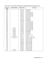
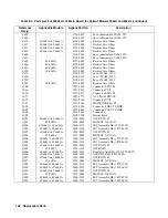
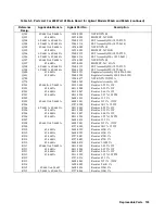
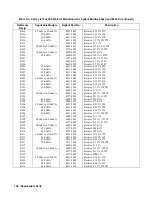
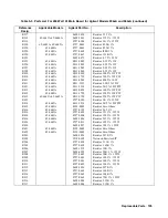
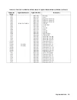
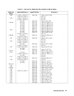
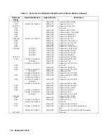
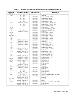
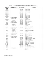
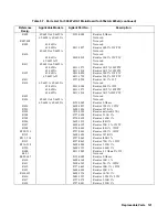
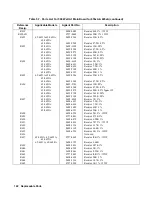
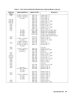
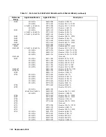
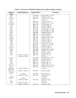
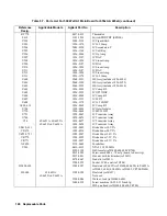
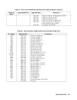
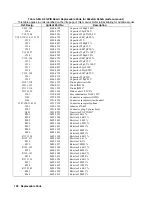
Table 5-6. Parts List For 500 Watt 655xA & 665xA Main Chassis (continued)
Reference
Desig.
Applicable Models
Agilent Part No.
Description
A3
6555A
06555-61001
Front Panel Board Initialized & Tested
6551A
06551-80001
Name plate
6552A
06552-80014
Name plate
6553A
06553-80001
Name plate
6554A
06554-80002
Name plate
6555A
06555-80001
Name plate
6651A
06651-8000l
Name plate
6652A
06652-80014
Name plate
6653A
06653-8000l
Name plate
6654A
06654-80002
Name plate
6655A
06655-8000l
Name plate
DSP1
5063-2304
LCD Display
Gl,G2
0960-0912
Optical Encoders (Rotary V and I controls)
5040-1665
Keypad
5063-3407
PCA Keypad
S1
3101-3088
AC line on/off switch
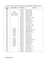
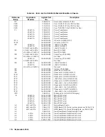
A4
Heat sink assembly
A4AI
Top Left Tunnel Board
65/6651A
06651-61022
Left Tunnel Board
65/6652A
06652-61022
Left Tunnel Board
65/6653A
06653-61022
Left Tunnel Board
65/6654A
06654-61002
Left Tunnel Board
65/6655A
06655-61022
Left Tunnel Board
A4A2
Top Right Tunnel Board
65/6651A
06651-61023
Right Tunnel Board
65/6652A
06652-61023
Right Tunnel Board
65/6653A
06653-61023
Right Tunnel Board
65/6654A
06654-61023
Right Tunnel Board
65/6655A
06655-61023
Right Tunnel Board
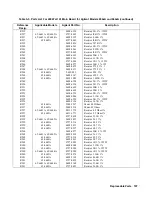
A4A3
Bottom Left Tunnel Board (same as A4A1)
A4A4
Bottom Right Tunnel Board (same as A4A2)
A4RT301
06652-60006
Thermistor assy (mounted on right hand top
side of heat sink assy)
5062-3704
Strap handle
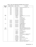
5041-8819
Cap - strap handle, front
5041-8820
Cap- strap handle, rear
5001-6748
Front panel dress
5040-1703
Front frame
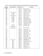
0515-0413
Screw mach M4 x 0.7 6 mm lg pan head (ref
rear panel, xfmr bracket, GPIB board)
5001-6771
Rear panel
06652-00004
Cover top
06652-00007
Bracket-transformer
06652-00008
Shroud for heat sink
06652-20001
Heat sink (ref A4 top and bottom)
06652-60001
Chassis
06652-60005
Jumper assy (ref xfmr Tl)
1400-0493
Cable tie (ref bias cable to front bracket)
1400-0528
Mount cable tie (ref front bracket)
Summary of Contents for 6541A
Page 12: ...12 Verification Figure 2 1 Basic Test Setup CV TESTS CV TESTS ...
Page 18: ...18 Verification Figure 2 3 CC RMS Noise Measurement Test Setup ...
Page 30: ......
Page 32: ...32 Troubleshooting Figure 3 1 Top View with Cover Removed for 655xA 665xA Models Sheet 1 of 2 ...
Page 33: ...Troubleshooting 33 Figure 3 1 Top View with Cover Removed for 655xA 665xA Models Sheet 2 of 2 ...
Page 37: ...Troubleshooting 37 Figure 3 2 Overall Troubleshooting Flow Diagram Sheet 1 of 4 ...
Page 38: ...38 Troubleshooting Figure 3 2 Overall Troubleshooting Flow Diagram Sheet 2 of 4 ...
Page 39: ...Troubleshooting 39 Figure 3 2 Overall Troubleshooting Flow Diagram Sheet 3 of 4 ...
Page 40: ...40 Troubleshooting Figure 3 2 Overall Troubleshooting Flow Diagram Sheet 4 of 4 ...
Page 51: ...Troubleshooting 51 Figure 3 5 No Display Troubleshooting ...
Page 52: ...52 Troubleshooting Figure 3 6 OV Will Not Fire Troubleshooting ...
Page 53: ...Troubleshooting 53 Figure 3 7 OV At Turn On Troubleshooting Sheet 1 of 2 ...
Page 54: ...54 Troubleshooting Figure 3 7 OV At Turn On Troubleshooting Sheet 2 of 2 ...
Page 55: ...Troubleshooting 55 Figure 3 8 Output Held Low Troubleshooting Sheet 1 of 2 ...
Page 56: ...56 Troubleshooting Figure 3 8 Output Held Low Troubleshooting Sheet 2 of 2 ...
Page 57: ...Troubleshooting 57 Figure 3 9 Output Held High Troubleshooting ...
Page 58: ...58 Troubleshooting Figure 3 10 DAC Circuits Troubleshooting ...
Page 60: ...60 Troubleshooting Figure 3 13 Serial Down Troubleshooting Sheet 1 of 2 ...
Page 61: ...Troubleshooting 61 Figure 3 13 Serial Down Troubleshooting Sheet 2 of 2 ...
Page 62: ...62 Troubleshooting Figure 3 14 Secondary Down Troubleshooting Sheet 1 of 2 ...
Page 63: ...Troubleshooting 63 Figure 3 14 Secondary Down Troubleshooting Sheet 2 of 2 ...
Page 64: ...64 Troubleshooting Figure 3 15 Slow Down Programming Troubleshooting ...
Page 65: ...Troubleshooting 65 Figure 3 16 Isolator Board Circuits Troubleshooting ...
Page 80: ......
Page 87: ...Principles of Operation 87 Figure 4 4 Output Power and Control Circuits ...
Page 94: ......
Page 136: ......
Page 145: ...Figure 6 1 Power Supply Interconnection Diagram for All Models ...
Page 146: ...Figure 6 2 AC Power Distribution Diagram for 655xA 665xA Models ...
Page 147: ...Figure 6 3 GPIB Board Assembly Diagram sheet 1 of 2 ...
Page 148: ...2 3 4 1 6 5 7 8 Figure 6 3 GPIB Board Schematic Diagram sheet 2 of 2 ...
Page 149: ...Figure 6 4 Front Panel Board Assembly Diagram sheet 1 of 2 ...
Page 150: ...Figure 6 4 Front Panel Board Schematic Diagram sheet 2 of 2 ...
Page 152: ...Figure 6 5 A1 Main Board Assembly Diagram for 654xA 664xA Models Only ...
Page 160: ...Figure 6 6 Left Tunnel Circuits Schematic Diagram for 654xA 664xA Models Only sheet 2 ...
Page 162: ...Figure 6 7 Right Tunnel Circuits Schematic Diagram for 654xA 664xA Models Only sheet 2 ...
Page 164: ......
Page 168: ......

