Replaceable Parts 125
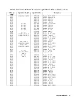
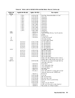
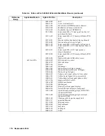
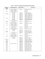
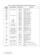
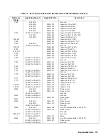
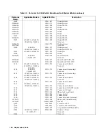
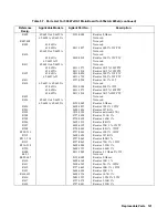
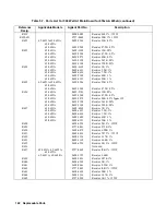
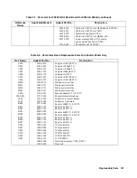
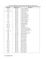
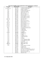
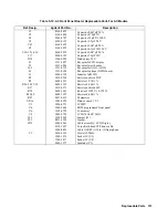
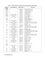
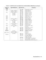
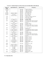
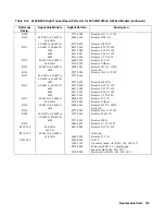
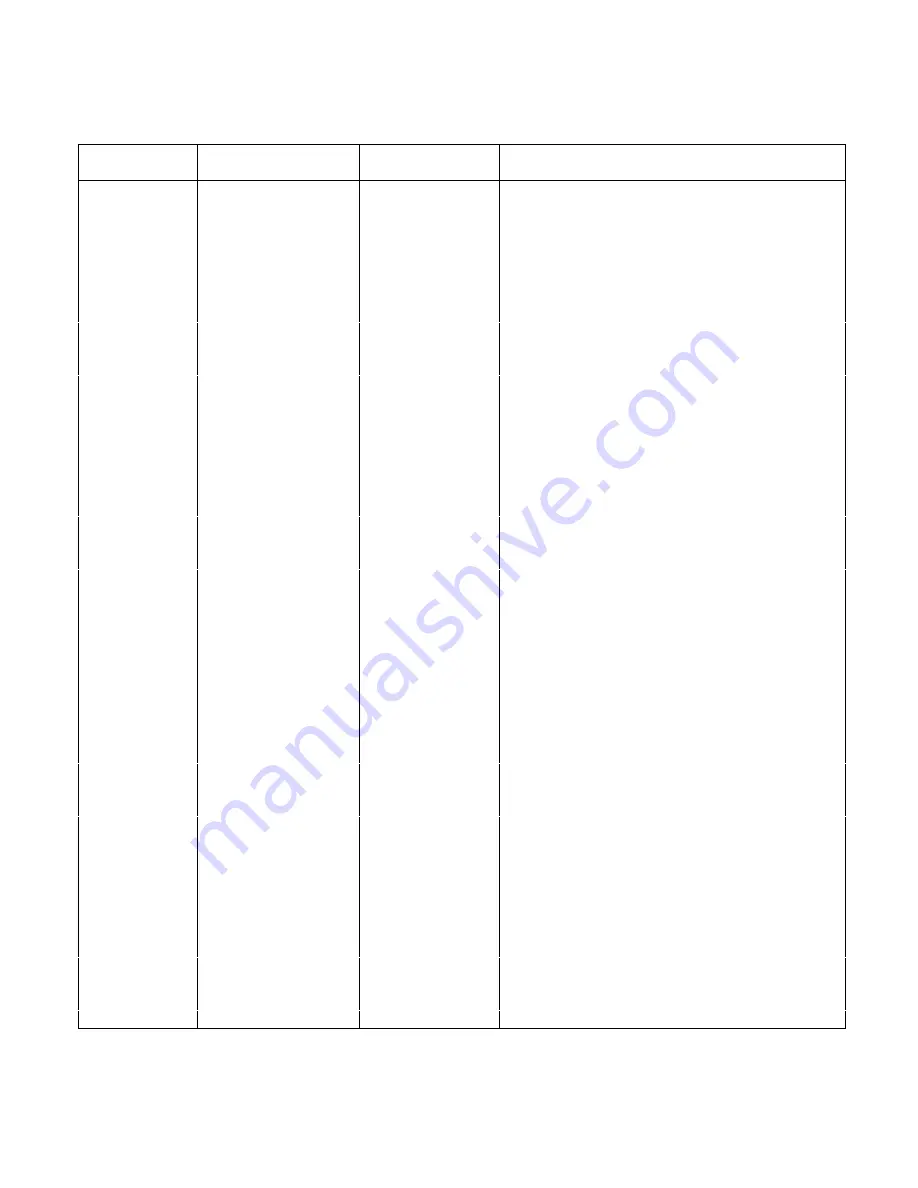
Table 5-7. Parts List For 500 Watt A1 Main Board for 655xA & 665xA (continued)
Reference
Desig.
Applicable Models
Agilent Part No.
Description
R715
0757-0280
Resistor 1K 1% .125W
R716
0698-0084
Resistor 2.15K 1%
R717,718
0698-3441
Resistor 215 1% .125W
R719
Not used
R720
0698-3151
Resistor 3.83K 1%
R721,722
0757-0280
Resistor 1K 1% .125W
R723,724
0698-3260
Resistor 464K 1%
R725
0698-3155
Resistor 4.64K 1%
R726
0698-3153
Resistor 3.83K 1%
R727
0757-0442
Resistor 10K 1% .125W
R728
0757-0449
Resistor 20K 1% .125W
R729
0757-0442
Resistor 10K 1% .125W
R730
0698-0084
Resistor 2.15K 1%
R731
0698-3260
Resistor 464K 1%
R732,733
0698-3155
Resistor 4.64K 1%
R734
0757-0442
Resistor l0K 1% .125W
R740,741
0698-3155
Resistor 4.64K 1%
R742
0757-0199
Resistor 21.5K 1%
R743
0757-0441
Resistor 8.25K 1%
R744
0757-0280
Resistor 1K 1% .125W
R745
0683-0475
Resistor 4.7 5% .25W
R746
0698-3162
Resistor 46.4K 1%
R747-749
0757-0199
Resistor 21.5K 1%
R750
0757-0280
Resistor 1K 1% .125W
R751
0683-0475
Resistor 4.7 5% .25W
R752
0698-3160
Resistor 31.6K 1%
R753
0757-0465
Resistor 100K 1%
R754
65/6651A, 65/6655A
0698-8816
Resistor 2.15 1%
65/6652A-65/6654A
Not used
R770,771
0757-0442
Resistor l0K 1% .125W
R772
0757-0470
Resistor 162K 1%
R773
0698-6376
Resistor 200K .1%
R774
0699-1212
Resistor 19K .1%
R775
0698-6630
Resistor 20K .1%
R778-779
0811-2201
Resistor 270 5% 2W PW
R781
0686-2225
Resistor 2.2K 5% .5W
R783, 784,
65/6651A-65/6653A
Not used
R786-788
R783, 784,
65/6654A, 65/6655A
8159-0005
Resistor 0 Ohms
R786-788
R785
65/6651A
0757-0405
Resistor 162 1%
65/6652A-65/6655A
0757-0397
Resistor 68.1 1%
R790
Not used
R789,791
65/6651A
Not used
65/6652A-65/6655A
8159-0005
Resistor 0 Ohms
R792
Not used
R793
65/6651A-65/6653A
Not used
65/6654A, 65/6655A
8159-0005
Resistor 0 Ohms
Summary of Contents for 6541A
Page 12: ...12 Verification Figure 2 1 Basic Test Setup CV TESTS CV TESTS ...
Page 18: ...18 Verification Figure 2 3 CC RMS Noise Measurement Test Setup ...
Page 30: ......
Page 32: ...32 Troubleshooting Figure 3 1 Top View with Cover Removed for 655xA 665xA Models Sheet 1 of 2 ...
Page 33: ...Troubleshooting 33 Figure 3 1 Top View with Cover Removed for 655xA 665xA Models Sheet 2 of 2 ...
Page 37: ...Troubleshooting 37 Figure 3 2 Overall Troubleshooting Flow Diagram Sheet 1 of 4 ...
Page 38: ...38 Troubleshooting Figure 3 2 Overall Troubleshooting Flow Diagram Sheet 2 of 4 ...
Page 39: ...Troubleshooting 39 Figure 3 2 Overall Troubleshooting Flow Diagram Sheet 3 of 4 ...
Page 40: ...40 Troubleshooting Figure 3 2 Overall Troubleshooting Flow Diagram Sheet 4 of 4 ...
Page 51: ...Troubleshooting 51 Figure 3 5 No Display Troubleshooting ...
Page 52: ...52 Troubleshooting Figure 3 6 OV Will Not Fire Troubleshooting ...
Page 53: ...Troubleshooting 53 Figure 3 7 OV At Turn On Troubleshooting Sheet 1 of 2 ...
Page 54: ...54 Troubleshooting Figure 3 7 OV At Turn On Troubleshooting Sheet 2 of 2 ...
Page 55: ...Troubleshooting 55 Figure 3 8 Output Held Low Troubleshooting Sheet 1 of 2 ...
Page 56: ...56 Troubleshooting Figure 3 8 Output Held Low Troubleshooting Sheet 2 of 2 ...
Page 57: ...Troubleshooting 57 Figure 3 9 Output Held High Troubleshooting ...
Page 58: ...58 Troubleshooting Figure 3 10 DAC Circuits Troubleshooting ...
Page 60: ...60 Troubleshooting Figure 3 13 Serial Down Troubleshooting Sheet 1 of 2 ...
Page 61: ...Troubleshooting 61 Figure 3 13 Serial Down Troubleshooting Sheet 2 of 2 ...
Page 62: ...62 Troubleshooting Figure 3 14 Secondary Down Troubleshooting Sheet 1 of 2 ...
Page 63: ...Troubleshooting 63 Figure 3 14 Secondary Down Troubleshooting Sheet 2 of 2 ...
Page 64: ...64 Troubleshooting Figure 3 15 Slow Down Programming Troubleshooting ...
Page 65: ...Troubleshooting 65 Figure 3 16 Isolator Board Circuits Troubleshooting ...
Page 80: ......
Page 87: ...Principles of Operation 87 Figure 4 4 Output Power and Control Circuits ...
Page 94: ......
Page 136: ......
Page 145: ...Figure 6 1 Power Supply Interconnection Diagram for All Models ...
Page 146: ...Figure 6 2 AC Power Distribution Diagram for 655xA 665xA Models ...
Page 147: ...Figure 6 3 GPIB Board Assembly Diagram sheet 1 of 2 ...
Page 148: ...2 3 4 1 6 5 7 8 Figure 6 3 GPIB Board Schematic Diagram sheet 2 of 2 ...
Page 149: ...Figure 6 4 Front Panel Board Assembly Diagram sheet 1 of 2 ...
Page 150: ...Figure 6 4 Front Panel Board Schematic Diagram sheet 2 of 2 ...
Page 152: ...Figure 6 5 A1 Main Board Assembly Diagram for 654xA 664xA Models Only ...
Page 160: ...Figure 6 6 Left Tunnel Circuits Schematic Diagram for 654xA 664xA Models Only sheet 2 ...
Page 162: ...Figure 6 7 Right Tunnel Circuits Schematic Diagram for 654xA 664xA Models Only sheet 2 ...
Page 164: ......
Page 168: ......

