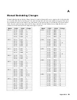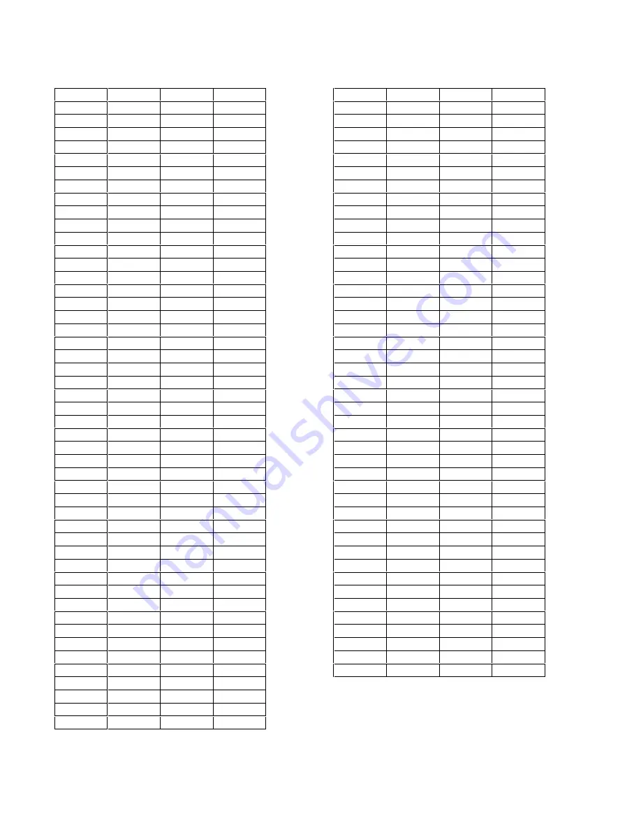
Model
Prefix
Serial
Change
6643A
3142A
00106
1
3215A
00121
5
3236A
00171
2
3346A
00436
16
3501A
00651
18
3619A
01146
24
6644A
3142A
00106
1
3219A
00116
5
3236A
00156
2
3346A
00291
16
3501A
00376
18
3620A
00696
24
6645A
3141A
00106
1
3215A
00111
5
3236A
00146
2
3346A
00231
16
3403A
00244
15
3501A
00373
18
3620A
00633
24
6651A
3049A
00111
3, 10
3130A
00171
11
3220A
00211
5
3241A
00231
2
3349A
00281
16
3501A
00396
18
3518A
00416
19
3542A
00466
20
3548A
00481
21
3603A
00531
22
3619A
00621
24
3620A
00626
25
6652A
3007A
00121
7
3021A
00151
8, 14
3035A
00231
3, 9
3127A
00321
11
3135A
00371
12, 13
3217A
00501
5
3235A
00631
2
3347A
01271
16
3501A
01721
18
3519A
02031
19
3541A
02361
20
3548A
02641
21, 22 *
3617A
02861
24, 25
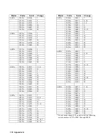
Model
Prefix
Serial
Change
6653A
3006A
00121
7
3020A
00171
8, 14
3035A
00331
3, 9
3120A
00381
6
3128A
00659
11
3136A
00491
12, 13
3216A
00661
5
3234A
00741
2
3347A
01091
16
3502A
01481
18
3548A
02121
21
3602A
02191
22
3619A
02361
24
3621A
02381
25
6654A
3007A
00121
7
3021A
00141
8, 14
3035A
00241
9
3036A
00251
3
3051A
00271
6
3114A
00311
11
3137A
00361
12, 13
3216A
00501
5
3236A
00561
2
3348A
00901
16
3502A
01191
18
3548A
01511
21
3602A
01541
22, 23
3619A
01761
24
3621A
01781
25
6655A
3050A
00111
3, 10
3113A
00126
6
3126A
00151
11
3126A
00176
1
3215A
00236
5
3235A
00261
2
3347A
00326
16
3403A
00351
15
3503A
00491
18
3548A
00586
21
3602A
00671
22, 23
3619A
00801
24
3622A
00811
25
* Do not make change #22 on units with the following
serial numbers: 3617A-02841 through 02845.
170 Appendix A
Summary of Contents for 6541A
Page 12: ...12 Verification Figure 2 1 Basic Test Setup CV TESTS CV TESTS ...
Page 18: ...18 Verification Figure 2 3 CC RMS Noise Measurement Test Setup ...
Page 30: ......
Page 32: ...32 Troubleshooting Figure 3 1 Top View with Cover Removed for 655xA 665xA Models Sheet 1 of 2 ...
Page 33: ...Troubleshooting 33 Figure 3 1 Top View with Cover Removed for 655xA 665xA Models Sheet 2 of 2 ...
Page 37: ...Troubleshooting 37 Figure 3 2 Overall Troubleshooting Flow Diagram Sheet 1 of 4 ...
Page 38: ...38 Troubleshooting Figure 3 2 Overall Troubleshooting Flow Diagram Sheet 2 of 4 ...
Page 39: ...Troubleshooting 39 Figure 3 2 Overall Troubleshooting Flow Diagram Sheet 3 of 4 ...
Page 40: ...40 Troubleshooting Figure 3 2 Overall Troubleshooting Flow Diagram Sheet 4 of 4 ...
Page 51: ...Troubleshooting 51 Figure 3 5 No Display Troubleshooting ...
Page 52: ...52 Troubleshooting Figure 3 6 OV Will Not Fire Troubleshooting ...
Page 53: ...Troubleshooting 53 Figure 3 7 OV At Turn On Troubleshooting Sheet 1 of 2 ...
Page 54: ...54 Troubleshooting Figure 3 7 OV At Turn On Troubleshooting Sheet 2 of 2 ...
Page 55: ...Troubleshooting 55 Figure 3 8 Output Held Low Troubleshooting Sheet 1 of 2 ...
Page 56: ...56 Troubleshooting Figure 3 8 Output Held Low Troubleshooting Sheet 2 of 2 ...
Page 57: ...Troubleshooting 57 Figure 3 9 Output Held High Troubleshooting ...
Page 58: ...58 Troubleshooting Figure 3 10 DAC Circuits Troubleshooting ...
Page 60: ...60 Troubleshooting Figure 3 13 Serial Down Troubleshooting Sheet 1 of 2 ...
Page 61: ...Troubleshooting 61 Figure 3 13 Serial Down Troubleshooting Sheet 2 of 2 ...
Page 62: ...62 Troubleshooting Figure 3 14 Secondary Down Troubleshooting Sheet 1 of 2 ...
Page 63: ...Troubleshooting 63 Figure 3 14 Secondary Down Troubleshooting Sheet 2 of 2 ...
Page 64: ...64 Troubleshooting Figure 3 15 Slow Down Programming Troubleshooting ...
Page 65: ...Troubleshooting 65 Figure 3 16 Isolator Board Circuits Troubleshooting ...
Page 80: ......
Page 87: ...Principles of Operation 87 Figure 4 4 Output Power and Control Circuits ...
Page 94: ......
Page 136: ......
Page 145: ...Figure 6 1 Power Supply Interconnection Diagram for All Models ...
Page 146: ...Figure 6 2 AC Power Distribution Diagram for 655xA 665xA Models ...
Page 147: ...Figure 6 3 GPIB Board Assembly Diagram sheet 1 of 2 ...
Page 148: ...2 3 4 1 6 5 7 8 Figure 6 3 GPIB Board Schematic Diagram sheet 2 of 2 ...
Page 149: ...Figure 6 4 Front Panel Board Assembly Diagram sheet 1 of 2 ...
Page 150: ...Figure 6 4 Front Panel Board Schematic Diagram sheet 2 of 2 ...
Page 152: ...Figure 6 5 A1 Main Board Assembly Diagram for 654xA 664xA Models Only ...
Page 160: ...Figure 6 6 Left Tunnel Circuits Schematic Diagram for 654xA 664xA Models Only sheet 2 ...
Page 162: ...Figure 6 7 Right Tunnel Circuits Schematic Diagram for 654xA 664xA Models Only sheet 2 ...
Page 164: ......
Page 168: ......


