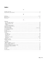
Signals
+5 V bias voltage.................................................................................................................................................91-93
BSTx.........................................................................................................................................................................93
CCPROG ..................................................................................................................................................................88
CVPROG..................................................................................................................................................................88
FAN PWM................................................................................................................................................................89
FAN PWM signal .....................................................................................................................................................89
IMON .......................................................................................................................................................................88
INHIBIT ...................................................................................................................................................................88
Output Control..........................................................................................................................................................86
OVCMP....................................................................................................................................................................85
OVPROG..................................................................................................................................................................85
OVSCR...............................................................................................................................................................85, 88
PCLR ..................................................................................................................................................................91, 92
+RAIL.......................................................................................................................................................................86
RESET*....................................................................................................................................................................92
RxD ................................................................................................................................................................... 91, 93
SPCLR* ..............................................................................................................................................................92, 93
SRx ...........................................................................................................................................................................93
TxD.....................................................................................................................................................................91, 93
VMON......................................................................................................................................................................88
XFMR T1 .................................................................................................................................................................92
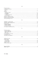
Slew rates.....................................................................................................................................................................11
SPCLR.........................................................................................................................................................................92
Specifications, operating manual ...................................................................................................................................9
T
TB101, terminal strip...................................................................................................................................................91
Test equipment required ..........................................................................................................................................9, 10
Test points .................................................................................................................................................................139
for Al main board ...................................................................................................................................................141
for A4A1/A4A3 left tunnel board...........................................................................................................................143
for A4A2/A4A4 right tunnel board.........................................................................................................................144
for GPIB board .......................................................................................................................................................140
for isolator board ....................................................................................................................................................140
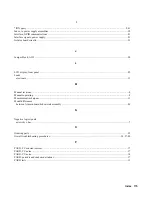
Test procedures.........................................................................................................................................................11
Test record tables.........................................................................................................................................................11
Tests
basic test set up .........................................................................................................................................................11
CC noise PARD........................................................................................................................................................17
CC setup ...................................................................................................................................................................15
CC source effect .......................................................................................................................................................17
current programming ................................................................................................................................................15
current sink operation and readback .........................................................................................................................16
CV load effect...........................................................................................................................................................14
CV Noise ..................................................................................................................................................................14
CV source effect .......................................................................................................................................................14
equipment required .....................................................................................................................................................9
load and line regulation ............................................................................................................................................16
operation verification................................................................................................................................................11
Index 177
Summary of Contents for 6541A
Page 12: ...12 Verification Figure 2 1 Basic Test Setup CV TESTS CV TESTS ...
Page 18: ...18 Verification Figure 2 3 CC RMS Noise Measurement Test Setup ...
Page 30: ......
Page 32: ...32 Troubleshooting Figure 3 1 Top View with Cover Removed for 655xA 665xA Models Sheet 1 of 2 ...
Page 33: ...Troubleshooting 33 Figure 3 1 Top View with Cover Removed for 655xA 665xA Models Sheet 2 of 2 ...
Page 37: ...Troubleshooting 37 Figure 3 2 Overall Troubleshooting Flow Diagram Sheet 1 of 4 ...
Page 38: ...38 Troubleshooting Figure 3 2 Overall Troubleshooting Flow Diagram Sheet 2 of 4 ...
Page 39: ...Troubleshooting 39 Figure 3 2 Overall Troubleshooting Flow Diagram Sheet 3 of 4 ...
Page 40: ...40 Troubleshooting Figure 3 2 Overall Troubleshooting Flow Diagram Sheet 4 of 4 ...
Page 51: ...Troubleshooting 51 Figure 3 5 No Display Troubleshooting ...
Page 52: ...52 Troubleshooting Figure 3 6 OV Will Not Fire Troubleshooting ...
Page 53: ...Troubleshooting 53 Figure 3 7 OV At Turn On Troubleshooting Sheet 1 of 2 ...
Page 54: ...54 Troubleshooting Figure 3 7 OV At Turn On Troubleshooting Sheet 2 of 2 ...
Page 55: ...Troubleshooting 55 Figure 3 8 Output Held Low Troubleshooting Sheet 1 of 2 ...
Page 56: ...56 Troubleshooting Figure 3 8 Output Held Low Troubleshooting Sheet 2 of 2 ...
Page 57: ...Troubleshooting 57 Figure 3 9 Output Held High Troubleshooting ...
Page 58: ...58 Troubleshooting Figure 3 10 DAC Circuits Troubleshooting ...
Page 60: ...60 Troubleshooting Figure 3 13 Serial Down Troubleshooting Sheet 1 of 2 ...
Page 61: ...Troubleshooting 61 Figure 3 13 Serial Down Troubleshooting Sheet 2 of 2 ...
Page 62: ...62 Troubleshooting Figure 3 14 Secondary Down Troubleshooting Sheet 1 of 2 ...
Page 63: ...Troubleshooting 63 Figure 3 14 Secondary Down Troubleshooting Sheet 2 of 2 ...
Page 64: ...64 Troubleshooting Figure 3 15 Slow Down Programming Troubleshooting ...
Page 65: ...Troubleshooting 65 Figure 3 16 Isolator Board Circuits Troubleshooting ...
Page 80: ......
Page 87: ...Principles of Operation 87 Figure 4 4 Output Power and Control Circuits ...
Page 94: ......
Page 136: ......
Page 145: ...Figure 6 1 Power Supply Interconnection Diagram for All Models ...
Page 146: ...Figure 6 2 AC Power Distribution Diagram for 655xA 665xA Models ...
Page 147: ...Figure 6 3 GPIB Board Assembly Diagram sheet 1 of 2 ...
Page 148: ...2 3 4 1 6 5 7 8 Figure 6 3 GPIB Board Schematic Diagram sheet 2 of 2 ...
Page 149: ...Figure 6 4 Front Panel Board Assembly Diagram sheet 1 of 2 ...
Page 150: ...Figure 6 4 Front Panel Board Schematic Diagram sheet 2 of 2 ...
Page 152: ...Figure 6 5 A1 Main Board Assembly Diagram for 654xA 664xA Models Only ...
Page 160: ...Figure 6 6 Left Tunnel Circuits Schematic Diagram for 654xA 664xA Models Only sheet 2 ...
Page 162: ...Figure 6 7 Right Tunnel Circuits Schematic Diagram for 654xA 664xA Models Only sheet 2 ...
Page 164: ......
Page 168: ......


