4
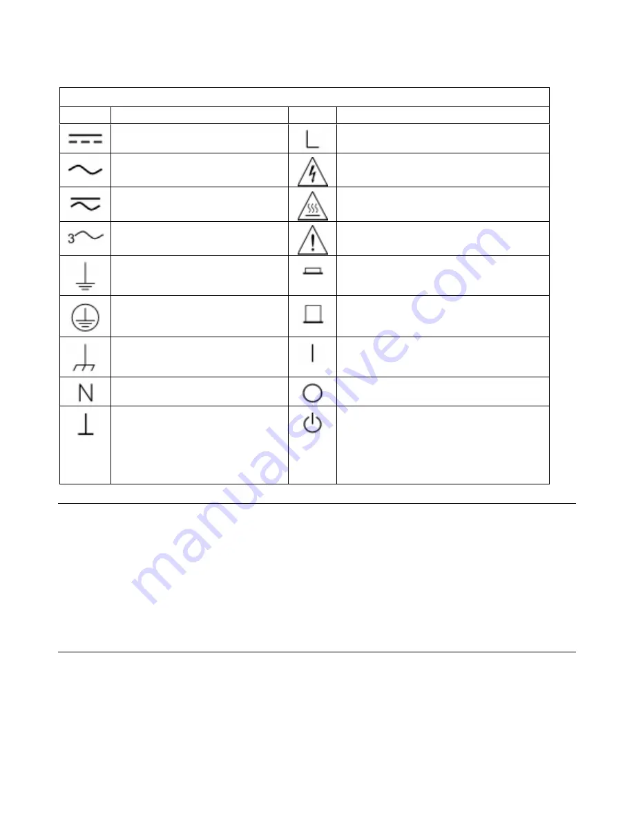
Safety Symbol Definitions
Symbol Description Symbol Description
Direct current
Terminal for Line conductor on permanently
installed equipment
Alternating current
Caution, risk of electric shock
Both direct and alternating current
Caution, hot surface
Three-phase alternating current
Caution (refer to accompanying documents)
Earth (ground) terminal
In position of a bi-stable push control
Protective earth (ground) terminal
(Intended for connection to external
protective conductor.)
Out position of a bi-stable push control
Frame or chassis terminal
On (supply)
Terminal for Neutral conductor on
permanently installed equipment
Off (supply)
Terminal is at earth potential
(Used for measurement and control
circuits designed to be operated with
one terminal at earth potential.)
Standby (supply)
Units with this symbol are not completely
disconnected from ac mains when this switch is
off. To completely disconnect the unit from ac
mains, either disconnect the power cord or have
a qualified electrician install an external switch.
Notice
The information contained in this document is subject to change without notice. Agilent Technologies makes no warranty of
any kind with regard to this material, including but not limited to, the implied warranties of merchantability, and fitness for a
particular purpose.
Agilent Technologies
shall not be liable for errors contained herein or for incidental or consequential damages in
connection with the furnishing, performance or use of this material.
This document contains proprietary information which is protected by copyright. All rights are reserved. No part of this
document may be photocopied, reproduced, or translated into another language without the prior written consent of Agilent
Technologies.
Copyright 1993, 2000 Agilent Technologies, Inc.
Printing History
The edition and current revision of this manual are indicated below. Reprints of this manual containing minor corrections
and updates may have the same printing date. Revised editions are identified by a new printing date. A revised edition
incorporates all new or corrected material since the previous printing date.
First Edition ............July, 1993
Second Edition ...... September, 2000
Summary of Contents for 6541A
Page 12: ...12 Verification Figure 2 1 Basic Test Setup CV TESTS CV TESTS ...
Page 18: ...18 Verification Figure 2 3 CC RMS Noise Measurement Test Setup ...
Page 30: ......
Page 32: ...32 Troubleshooting Figure 3 1 Top View with Cover Removed for 655xA 665xA Models Sheet 1 of 2 ...
Page 33: ...Troubleshooting 33 Figure 3 1 Top View with Cover Removed for 655xA 665xA Models Sheet 2 of 2 ...
Page 37: ...Troubleshooting 37 Figure 3 2 Overall Troubleshooting Flow Diagram Sheet 1 of 4 ...
Page 38: ...38 Troubleshooting Figure 3 2 Overall Troubleshooting Flow Diagram Sheet 2 of 4 ...
Page 39: ...Troubleshooting 39 Figure 3 2 Overall Troubleshooting Flow Diagram Sheet 3 of 4 ...
Page 40: ...40 Troubleshooting Figure 3 2 Overall Troubleshooting Flow Diagram Sheet 4 of 4 ...
Page 51: ...Troubleshooting 51 Figure 3 5 No Display Troubleshooting ...
Page 52: ...52 Troubleshooting Figure 3 6 OV Will Not Fire Troubleshooting ...
Page 53: ...Troubleshooting 53 Figure 3 7 OV At Turn On Troubleshooting Sheet 1 of 2 ...
Page 54: ...54 Troubleshooting Figure 3 7 OV At Turn On Troubleshooting Sheet 2 of 2 ...
Page 55: ...Troubleshooting 55 Figure 3 8 Output Held Low Troubleshooting Sheet 1 of 2 ...
Page 56: ...56 Troubleshooting Figure 3 8 Output Held Low Troubleshooting Sheet 2 of 2 ...
Page 57: ...Troubleshooting 57 Figure 3 9 Output Held High Troubleshooting ...
Page 58: ...58 Troubleshooting Figure 3 10 DAC Circuits Troubleshooting ...
Page 60: ...60 Troubleshooting Figure 3 13 Serial Down Troubleshooting Sheet 1 of 2 ...
Page 61: ...Troubleshooting 61 Figure 3 13 Serial Down Troubleshooting Sheet 2 of 2 ...
Page 62: ...62 Troubleshooting Figure 3 14 Secondary Down Troubleshooting Sheet 1 of 2 ...
Page 63: ...Troubleshooting 63 Figure 3 14 Secondary Down Troubleshooting Sheet 2 of 2 ...
Page 64: ...64 Troubleshooting Figure 3 15 Slow Down Programming Troubleshooting ...
Page 65: ...Troubleshooting 65 Figure 3 16 Isolator Board Circuits Troubleshooting ...
Page 80: ......
Page 87: ...Principles of Operation 87 Figure 4 4 Output Power and Control Circuits ...
Page 94: ......
Page 136: ......
Page 145: ...Figure 6 1 Power Supply Interconnection Diagram for All Models ...
Page 146: ...Figure 6 2 AC Power Distribution Diagram for 655xA 665xA Models ...
Page 147: ...Figure 6 3 GPIB Board Assembly Diagram sheet 1 of 2 ...
Page 148: ...2 3 4 1 6 5 7 8 Figure 6 3 GPIB Board Schematic Diagram sheet 2 of 2 ...
Page 149: ...Figure 6 4 Front Panel Board Assembly Diagram sheet 1 of 2 ...
Page 150: ...Figure 6 4 Front Panel Board Schematic Diagram sheet 2 of 2 ...
Page 152: ...Figure 6 5 A1 Main Board Assembly Diagram for 654xA 664xA Models Only ...
Page 160: ...Figure 6 6 Left Tunnel Circuits Schematic Diagram for 654xA 664xA Models Only sheet 2 ...
Page 162: ...Figure 6 7 Right Tunnel Circuits Schematic Diagram for 654xA 664xA Models Only sheet 2 ...
Page 164: ......
Page 168: ......


