Principles of Operation 91
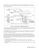
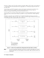
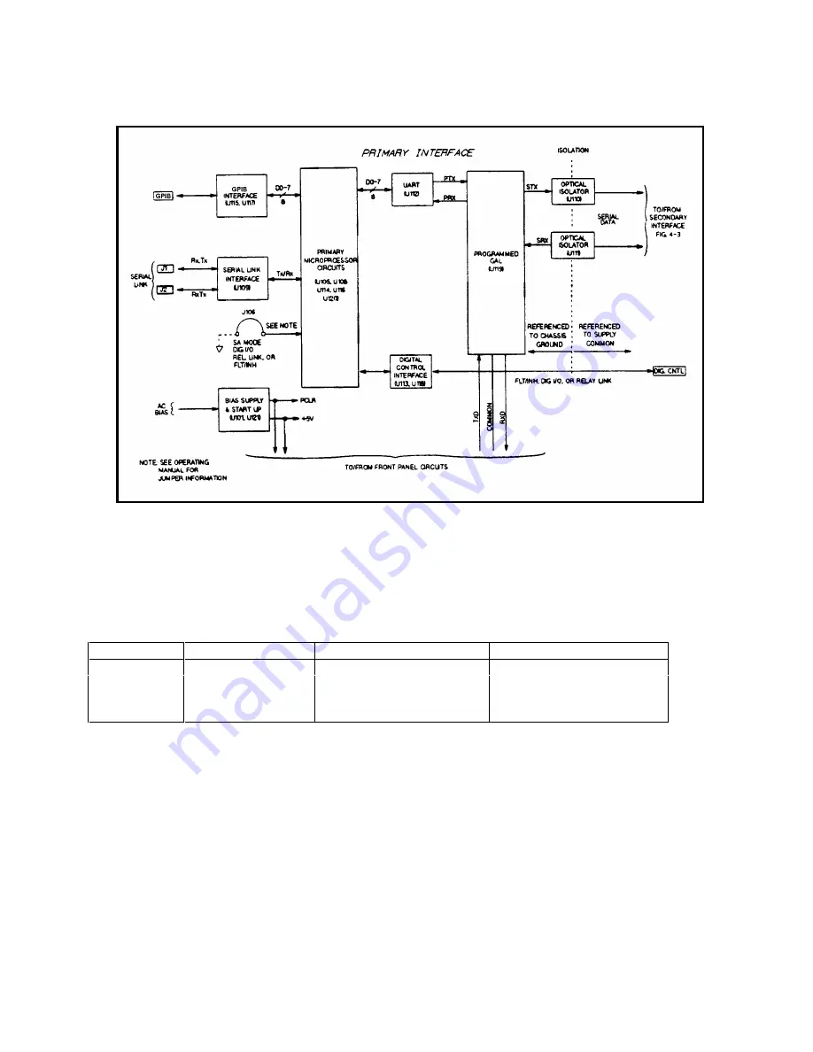
Figure 4-6. GPIB Board, Simplified Block Diagram (Models Agilent 664xA and 665xA Only)
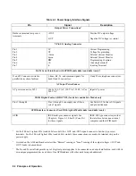
Terminal strip TB101 can be strapped to provide one of four digital input/output control signals (see Table 4-4). The Power
Supply Operating Manual describes how to select one of these three sets of signals. As shipped from the factory, this
terminal strip is connected for FLT output and INH input. Refer to the Operating Manual for operating instructions.
Table 4-4. TB101 Terminal Strip, Digital CNTL Signals
PIN
Digital I/O
Relay Link
Fault/Isolation
Pin 1
OUT 0
RLY SEND
FLT Output
Pin 2
OUT 1
NC
FLT Common
Pin 3
IN/OUT 2
RLY RTN
INH Input
Pin 4
Common
Common
INH Common
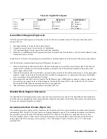
The bias supply (+5 V reference to earth ground) for the primary interface circuits is located on the A2 board. It also
provides the bias voltage to operate the circuits located on the front panel board, the LCD, and the keypad. A power clear
signal (PCLR) is generated to initialize certain primary interface circuits and front panel circuits when the unit is turned on.
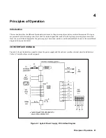
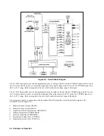
Isolator Board Circuits for Agilent Models 654xA and 665xA Only (Figure 4-7)
The isolator board performs the following two functions:
1.
Creates a +5 V bias voltage.
2.
Provides isolation between the PCLR, RxD, and TxD front panel signals and similar signals received from the A1 Main
Board.
Summary of Contents for 6541A
Page 12: ...12 Verification Figure 2 1 Basic Test Setup CV TESTS CV TESTS ...
Page 18: ...18 Verification Figure 2 3 CC RMS Noise Measurement Test Setup ...
Page 30: ......
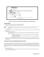
Page 32: ...32 Troubleshooting Figure 3 1 Top View with Cover Removed for 655xA 665xA Models Sheet 1 of 2 ...
Page 33: ...Troubleshooting 33 Figure 3 1 Top View with Cover Removed for 655xA 665xA Models Sheet 2 of 2 ...
Page 37: ...Troubleshooting 37 Figure 3 2 Overall Troubleshooting Flow Diagram Sheet 1 of 4 ...
Page 38: ...38 Troubleshooting Figure 3 2 Overall Troubleshooting Flow Diagram Sheet 2 of 4 ...
Page 39: ...Troubleshooting 39 Figure 3 2 Overall Troubleshooting Flow Diagram Sheet 3 of 4 ...
Page 40: ...40 Troubleshooting Figure 3 2 Overall Troubleshooting Flow Diagram Sheet 4 of 4 ...
Page 51: ...Troubleshooting 51 Figure 3 5 No Display Troubleshooting ...
Page 52: ...52 Troubleshooting Figure 3 6 OV Will Not Fire Troubleshooting ...
Page 53: ...Troubleshooting 53 Figure 3 7 OV At Turn On Troubleshooting Sheet 1 of 2 ...
Page 54: ...54 Troubleshooting Figure 3 7 OV At Turn On Troubleshooting Sheet 2 of 2 ...
Page 55: ...Troubleshooting 55 Figure 3 8 Output Held Low Troubleshooting Sheet 1 of 2 ...
Page 56: ...56 Troubleshooting Figure 3 8 Output Held Low Troubleshooting Sheet 2 of 2 ...
Page 57: ...Troubleshooting 57 Figure 3 9 Output Held High Troubleshooting ...
Page 58: ...58 Troubleshooting Figure 3 10 DAC Circuits Troubleshooting ...
Page 60: ...60 Troubleshooting Figure 3 13 Serial Down Troubleshooting Sheet 1 of 2 ...
Page 61: ...Troubleshooting 61 Figure 3 13 Serial Down Troubleshooting Sheet 2 of 2 ...
Page 62: ...62 Troubleshooting Figure 3 14 Secondary Down Troubleshooting Sheet 1 of 2 ...
Page 63: ...Troubleshooting 63 Figure 3 14 Secondary Down Troubleshooting Sheet 2 of 2 ...
Page 64: ...64 Troubleshooting Figure 3 15 Slow Down Programming Troubleshooting ...
Page 65: ...Troubleshooting 65 Figure 3 16 Isolator Board Circuits Troubleshooting ...
Page 80: ......
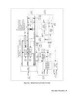
Page 87: ...Principles of Operation 87 Figure 4 4 Output Power and Control Circuits ...
Page 94: ......
Page 136: ......
Page 145: ...Figure 6 1 Power Supply Interconnection Diagram for All Models ...
Page 146: ...Figure 6 2 AC Power Distribution Diagram for 655xA 665xA Models ...
Page 147: ...Figure 6 3 GPIB Board Assembly Diagram sheet 1 of 2 ...
Page 148: ...2 3 4 1 6 5 7 8 Figure 6 3 GPIB Board Schematic Diagram sheet 2 of 2 ...
Page 149: ...Figure 6 4 Front Panel Board Assembly Diagram sheet 1 of 2 ...
Page 150: ...Figure 6 4 Front Panel Board Schematic Diagram sheet 2 of 2 ...
Page 152: ...Figure 6 5 A1 Main Board Assembly Diagram for 654xA 664xA Models Only ...
Page 160: ...Figure 6 6 Left Tunnel Circuits Schematic Diagram for 654xA 664xA Models Only sheet 2 ...
Page 162: ...Figure 6 7 Right Tunnel Circuits Schematic Diagram for 654xA 664xA Models Only sheet 2 ...
Page 164: ......
Page 168: ......

