Getting Started
37
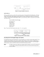
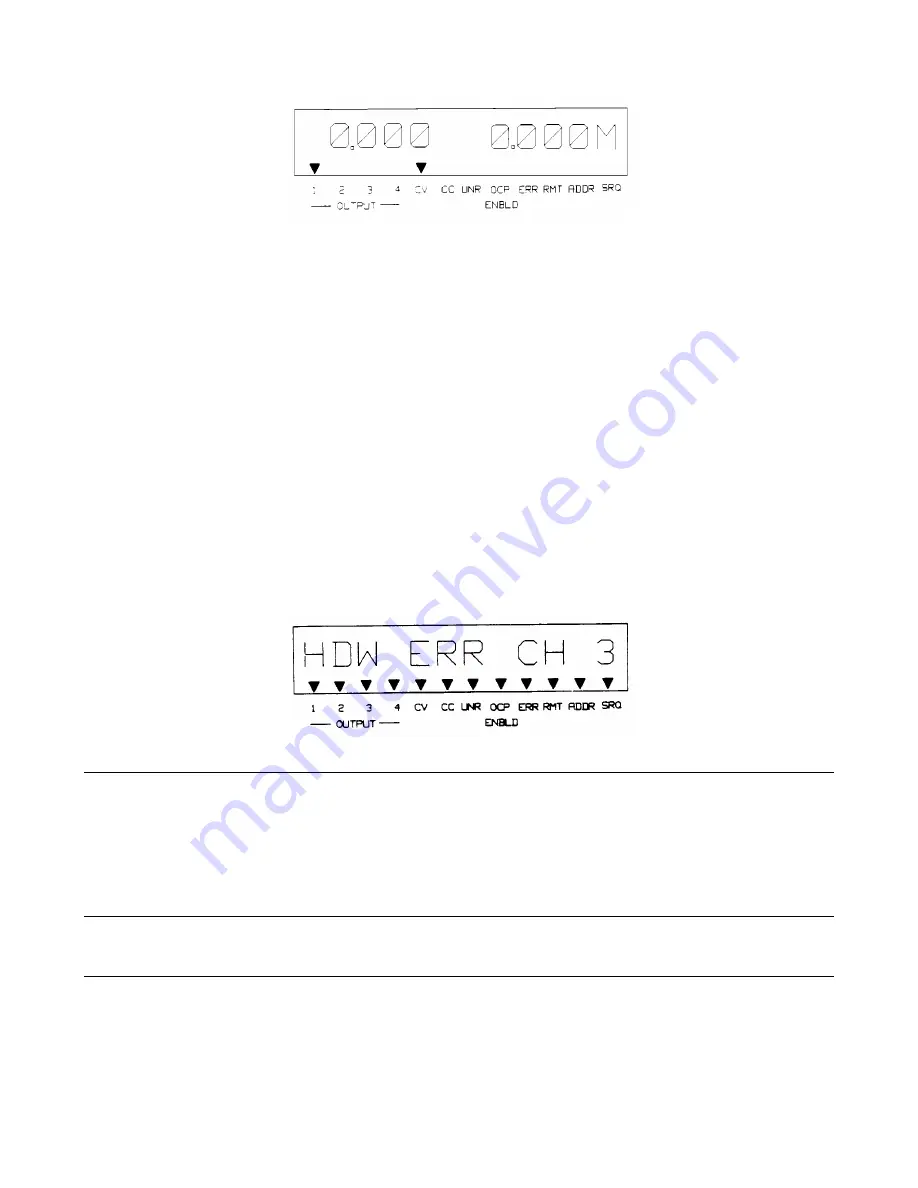
Figure 3-4. Typical Display at Power-On
Self-Test Errors
If the supply fails the power-on self-test, all power supply outputs will remain disabled (off) and the display will indicate
the type of failure and the output channel on which it occurred. Figure 3-5 shows that self-test detected an error in output
channel 3. Error messages that could appear on the display if self-test fails are listed below. Self-test error messages are
explained in Appendix D and troubleshooting procedures are given in the Service Manual. You may also call your Agilent
Sales Office for help.
Power-On Self Test Error Messages
HDW ERR CH "N"
8291 FAILED
TIMER FAILED
CV DAC CH ’’N"
CC DAC CH "N"
OV DAC CH "N"
FUSE CH ’’N"
Note: "N" specifies the failed output channel number: 1,2,3, or 4 as applicable.
Figure 3-5. Sample Self-Test Failure Display
Checking Out Your Supply Using Local Control
The following procedures use the display and keys on the front panel to check each of your power supply’s outputs. No test
equipment, other than a jumper wire (14 AWG), is required to perform these tests. The tests must be repeated for each
output of your particular supply. The checkout consists of voltage, overvoltage, and current tests. It is assumed that power
has already been turned on, the supply has passed the power-on self-test, loads are not connected to any of the supply’s
outputs, and sense clips are connected between the sense terminals and the output terminals.
Note
The following procedures are identical for all models and for all outputs. Use the OUTPUT SELECT key
to select an output to be tested. If an output fails any of the tests, refer to the troubleshooting section in
the Service Manual.
Summary of Contents for 6625A
Page 10: ......
Page 24: ......
Page 30: ......
Page 44: ......
Page 62: ......
Page 68: ...Remote Operation 68 Figure 5 2 Sheet 1 of 2 Syntax Forms For Power Supply Commands ...
Page 69: ...Remote Operation 69 Figure 5 2 Sheet 2 of 2 Syntax Forms For Power Supply Commands ...
Page 90: ......
Page 94: ...Alignment Procedures 94 Figure A 3 Figure A 4 Figure A 5 ...
Page 116: ......
Page 120: ......

