background image

Specifications

Definition of Terms

80

Agilent 

81950A Compact TLS module, First Edition

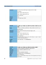
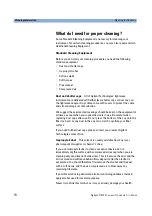
Polarization extinction ratio

Specifies the ratio of the optical power in the slow axis of a connected 
polarization-maintaining fiber to optical power in the fast axis, expressed 
in dB

Conditions:

Applicable to tunable laser sources utilizing polarization maintaining fiber 
that has its TE mode in the slow axis and aligned with the connector key. 

Measurement:

Using a polarization analyzer at the end of a polarization-maintaining 
patchcord, by sweeping the wavelength to create circular traces on the 
Poincaré sphere. Calculate the polarization extinction ratio from the 
diameters of these circles.

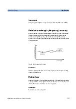
Figure 6  Circular traces on the Poincaré sphere used to calculate polarization extinction ra-

tio.

Summary of Contents for 81950A

Page 1: ...Agilent Technologies Agilent 81950A Compact Tunable Laser Source module User s Guide ...

Page 2: ...ent that conflict with these terms the warranty terms in the separate agreement shall control Limitation of Warranty The foregoing warranty shall not apply to defects resulting from improper or inadequate maintenance by Buyer Buyer supplied software or interfacing unauthorized modification or misuse operation outside of the environmental specifications for the product or improper site preparation ...

Page 3: ...u can also contact one of the following centers and ask for a test and measurement sales representative United States 1 800 829 4444 1 800 829 4433 FAX Canada 1 877 894 4414 1 905 282 6495 FAX Europe 31 20 547 2111 31 20 547 2190 FAX Japan 120 421 345 120 421 678 FAX Mexico 52 55 5081 9469 52 55 5081 9467 FAX Australia 800 629 485 800 142 134 FAX Asia Pacific 852 800 930 871 852 2 506 9233 FAX Lat...

Page 4: ...This chapter provides a general description of the specific features of the 81950A compact tunable laser module Chapter 4 Programming Instructions This chapter describes the SCPI Commands for use of 81950A compact tunable laser modules and N7711A N7714A single and 4 port Tunable Laser System Sources Chapter 5 Specifications This chapter contains the specifications of the 81950A module Chapter 6 Cl...

Page 5: ... Safety Information for Tunable Laser Modules 15 Laser Safety Labels 16 Laser class 1M label 16 Introduction 17 What is a Tunable Laser Source 17 Installation 17 Front Panels 17 Front Panel Controls and Indicators 18 Typical Use Models 19 Optical Output 21 Polarization Maintaining Fiber 21 Angled and Straight Contact Connectors 22 Signal Input and Output 23 Accessories 25 Modules and Options 26 Mo...

Page 6: ... 37 How to Set the Power 39 How to Switch Operation Mode 40 How to Set the Wavelength or Frequency 43 How to Switch On the Laser 44 How to set Frequency Parameters in Grid Mode 45 How to Check the Output Frequency or Wavelength 46 How to Modulate a Signal 47 The User Interface 49 The Module s Front Panel 49 Programming Instructions 51 Summary 52 Detailed Description 54 The OUTPut sub tree 54 The S...

Page 7: ...atability 81 Power stability 82 Relative intensity noise RIN 82 Relative wavelength frequency accuracy 83 Return loss 83 SBS suppression effective linewidth 84 Side mode suppression ratio 84 Signal to source spontaneous emission ratio 84 Tuning time 85 Wavelength range 85 Wavelength frequency repeatability 86 Wavelength resolution 86 Wavelength frequency stability 86 Compact Tunable Laser Module S...

Page 8: ...ent Housings 98 Which Cleaning Procedure should I use 99 How to clean connectors 100 How to clean connector interfaces 102 How to clean bare fiber adapters 103 How to clean instruments with a fixed connector interface 104 Additional Cleaning Information 105 Other Cleaning Hints 106 Index 107 ...

Page 9: ...Agilent 81950A Compact TLS module First Edition 9 ...

Page 10: ...10 Agilent 81950A Compact TLS module First Edition ...

Page 11: ...quirements 13 Operating Environment 13 Input Output Signals 14 Storage and Shipment 14 Initial Safety Information for Tunable Laser Modules 15 Laser Safety Labels 16 Introduction 17 What is a Tunable Laser Source 17 Installation 17 Front Panels 17 Front Panel Controls and Indicators 18 Typical Use Models 19 Optical Output 21 Polarization Maintaining Fiber 21 Angled and Straight Contact Connectors ...

Page 12: ...e operation review the instrument and manual including the red safety page for safety markings and instructions You must follow these to ensure safe operation and to maintain the instrument in safe condition Safety Symbols The apparatus will be marked with this symbol when it is necessary for the user to refer to the instruction manual in order to protect the apparatus against damage Hazardous las...

Page 13: ...ilent 81950A Compact Tunable Laser Source modules operate when installed in Agilent 8163A B Lightwave Multimeters Agilent 8164A B Lightwave Measurement Systems and Agilent 8166A B Lightwave Multichannel Systems Operating Environment The safety information in your mainframe s User s Guide summarizes the operating ranges for the Agilent 81950A Compact Tunable Laser Source modules In order for these ...

Page 14: ...module can be stored or shipped at temperatures between 40 C and 70 C Protect the module from temperature extremes that may cause condensation within it There is one BNC input connector on the front panel of an Agilent 81950A Compact Tunable Laser Source module To prevent the BNC interface from damage do not exceed the voltage limit of 5V when applying external voltage CAUTION ...

Page 15: ...No 50 dated 2001 July 26 Agilent 81950A Option 210 Agilent 81950A Option 201 Laser Type ECL Laser InGaAsP ECL Laser InGaAsP Wavelength range 1527nm 1566nm 1570nm 1609nm Max CW output power 50 mW 50 mW Beam waist diameter 9 μm 9 μm Numerical aperture 0 1 0 1 Laser Class according to IEC 60825 1 2001 Intl 1M 1M Max permissible CW output power 163 mW 163 mW Max CW output power is defined as the highe...

Page 16: ...ng Under no circumstances look into the end of an optical cable attached to the optical output when the device is operational The laser radiation can seriously damage your eyesight Do not enable the laser when there is no fiber attached to the optical output connector The laser is enabled by pressing the active button close to the optical output connector on the front panel of the module The laser...

Page 17: ...ent Technologies range of compact TLS modules are flexible stimulus modules suitable for applications such as the testing of optical amplifiers DWDM components and complete DWDM systems Installation The Agilent 81950A Compact TLS module is a front loadable module For a description of how to install your module refer to How to Fit and Remove Modules in the Installation and Maintenance chapter of yo...

Page 18: ...dicators Switch the laser source on or off using the switch on its front panel using the State parameter in the instrument s Graphical User Interface or remotely using SCPI commands When the Active LED is lit the source is emitting radiation When the Active LED is not lit the source is not emitting radiation ...

Page 19: ...under test itself Thus engineers can test optical amplifiers such as EDFAs Raman amplifiers SOAs and EDWAs to their limits This tunable laser provides the high power levels required to help speed the development of innovative devices by enabling the test and measurement of nonlinear effects Low linewidth source for complex modulation formats The low linewidth of the Agilent 81950A Compact TLS modu...

Page 20: ...Getting Started Typical Use Models 20 Agilent 81950A Compact TLS module First Edition Specifications For further details on specifications see the Specifications on page 75 ...

Page 21: ...o maintain the state of polarization A well defined state of polarization helps ensure constant measurement conditions The fiber is of Panda type with TE mode in the slow axis in line with the connector key See Chapter 2 Modules and Options for further details on connector interfaces and accessories Figure 3 PMF Output Connector E H Slow Axis Polarization Axis Connector Key Fiber Cladding Fiber Co...

Page 22: ...he angled contact connector symbol is colored green You should connect straight contact fiber end connectors with neutral sleeves to straight contact connectors and connect angled contact fiber end connectors with green sleeves to angled contact connectors See Connector Interfaces on page 28 for further details on connector interfaces and accessories If the contact connector on your instrument is ...

Page 23: ...ule First Edition 23 Signal Input and Output There is one BNC input connector on the front panel of an Agilent 81950A Compact Tunable Laser Source module To prevent the BNC interface from damage do not exceed the voltage limit of 5V when applying external voltage CAUTION ...

Page 24: ...Getting Started Signal Input and Output 24 Agilent 81950A Compact TLS module First Edition ...

Page 25: ...ailable in various configurations for the best possible match to the most common applications This chapter provides information on the available options and accessories Modules and Options 26 Modules 27 Options 27 Option 210 27 Option 201 27 Connector Interfaces 28 Option 071 28 Option 072 28 User s Guides 29 ...

Page 26: ...1465 nm 1575 nm 81949A Compact Tunable Laser 1520 nm 1630 nm Connector Interfaces for angled connectors 1 ea required 81000FI FC APC keywidth 2 2mm 81000NI FC APC keywidth 2 0mm 81000HI E 2000 APC 81000KI SC APC 81000LI LC APC 81000MI MU APC 81000SI DIN 47256 APC 81000VI ST APC Connector Interfaces for straight connectors Note 819xxA 072 is highly recommended over 819xxA 071 to reduce front panel ...

Page 27: ...le Laser C band 1527 1566nm Option 201 High Power Tunable Laser L band 1570 1609nm Option 071 Polarization maintaining fiber Panda type for straight contact connectors Option 072 Polarization maintaining fiber Panda type for angled contact connectors Table 1 Compact Tunable Laser Modules Model Number Description Agilent 81950A Option 210 High Power Compact Tunable Laser 1527 nm 1566 nm Agilent 819...

Page 28: ...e Option 072 Angled Contact Connectors If you want to use angled connectors such as E 2000 APC SC APC FC APC or DIN 4108 6 4108 6 to connect to the instrument you must do the following 1 Attach your connector interface to the interface adapter 2 See Table 3 for a list of the available connector interfaces 3 Connect your cable Table 2 Straight Contact Connector Interfaces Description Model number F...

Page 29: ...e 81950 91020 Agilent 8163A B Lightwave Multimeter Agilent 8164A B Lightwave Measurement System Agilent 8166A B Lightwave Multichannel System User s Guide 08164 90B15 Agilent 8163A B Lightwave Multimeter Agilent 8164A B Lightwave Measurement System Agilent 8166A B Lightwave Multichannel System Programming Guide 08164 90B64 Agilent 8163B Lightwave Multimeter Agilent 8164B Lightwave Measurement Syst...

Page 30: ...Accessories User s Guides 30 Agilent 81950A Compact TLS module First Edition ...

Page 31: ... Switching Modes 34 Preset Values 35 Differences to Other Tunable Laser Source Modules 35 The Graphical User Interface 36 Differences among 8164A B 8163A B and 8166A B 36 Soft Lock 36 How to Set a Parameter 37 How to Set the Power 39 How to Switch Operation Mode 40 How to Set the Wavelength or Frequency 43 How to Switch On the Laser 44 How to set Frequency Parameters in Grid Mode 45 How to Check t...

Page 32: ...2 Agilent 81950A Compact TLS module First Edition Symbols used in this chapter Symbols Description wavelength frequency reference frequency frequency offset grid spacing channel number i e ITU grid channel number λ f fo Δf s c ...

Page 33: ...aling or trace tone AM level The AM modulation is only available with the Agilent 81950A module using the BNC connector at the module s front panel The N7711A N7714A instruments platform features no such connector Output Frequency The output frequency is calculated using this equation Limitations Reference frequency and grid spacing can only be changed when the laser is off Operation mode can only...

Page 34: ...t want to set a frequency or wavelength without thinking about the details So the instrument offers two operation modes Auto Mode and Grid Mode Auto Mode You can set a frequency or wavelength and the instrument calculates and sets its parameters accordingly and are read only Grid Mode You can set and s manually You can also edit and to get the desired frequency The resulting output frequency and w...

Page 35: ...on off FM 0 AM 0 Differences to Other Tunable Laser Source Modules The 81950A compact tunable laser source modules are intended for use as a highly stable high power laser source They use a different technology which makes them slower when switching on the laser or changing the power or wavelength The 81950A tunable lasers do not support wavelength sweeps and triggering Besides they have different...

Page 36: ... Modulation group boxes hidden 8163A 8166A Grid Output and Modulation group boxes hidden Soft Lock When you use high power Tunable Laser Source modules you must enter the password to unlock the instrument This feature is called Soft Lock as opposed to a lock using a key At power on the instrument shows a dialog and prompts the user to enter a code to unlock it Later you can lock or unlock the inst...

Page 37: ...meter you want to change using the arrow keys or the Modify Knob For some parameters you can now change the unit e g W dBm for power or switch between frequency and wavelength using the soft keys Press Enter the Modify Knob or the Edit soft key to start editing the value Enter the desired value using the Up Down Left Right keys the Modify Knob or the numerical key pad When finished press Enter the...

Page 38: ...Operating Instructions The Graphical User Interface 38 Agilent 81950A Compact TLS module First Edition ...

Page 39: ... module First Edition 39 How to Set the Power Move to the power parameter P If you want to change the unit W dBm or vice versa press the Pwr unit soft key Use the Pmax soft key to set the maximum power or Change the value as described in chapter How to Set a Parameter on page 37 ...

Page 40: ...to select an operation mode When finished press Enter the Modify Knob or the OK soft key You can also cancel the operation using the Cancel soft key 8163 A B 8166 A B Note This also works on the 8164 A B though it is not necessary to use the menu there Press the Menu soft key then use the Up or Down button to move to parameter Auto Mode Press the OK soft key Use the Up or Down key to select an ope...

Page 41: ...The Graphical User Interface Operating Instructions Agilent 81950A Compact TLS module First Edition 41 Details Screen in Auto Mode ...

Page 42: ...Operating Instructions The Graphical User Interface 42 Agilent 81950A Compact TLS module First Edition Details Screen in Grid Mode i e Auto Mode off ...

Page 43: ...s applies to Auto Mode only For more information refer to the chapters Operation Modes on page 34 and How to Switch Operation Mode on page 40 Move to parameter wavelength or frequency If you want to switch from wavelength to frequency or back press the Freq Wvl soft key Change the value as described in chapter How to Set a Parameter 37 on page 31 λ f ...

Page 44: ...line refer to chapter Soft Lock on page 36 Move to parameter state Press Enter the Modify Knob or the Edit soft key to start editing the value Use the Up or Down key or the Modify Knob to select the laser state When finished press Enter the Modify Knob or the OK soft key You can also cancel the operation using the Cancel soft key You can also use the module s front panel key to switch the laser st...

Page 45: ...most line is the channel number Ch The resulting output frequency must be set using the reference frequency grid spacing frequency offset and channel number Move to the parameter you want to change it may be necessary to open the menu by pressing the Menu soft key to access it Change the value as described in chapter How to Set a Parameter on page 37 Reference frequency and grid spacing can only b...

Page 46: ...interesting to know the output frequency or wavelength e g if you edit the channel number or frequency you might want to know the corresponding wavelength Depending on the instrument type and state these values are displayed in the Output group box on the Details Screen or can be checked in the menu Press the Menu soft key to open the menu These values are read only NOTE ...

Page 47: ...l Signaling parameter AM lvl can make use of an AM modulation signal supplied via the BNC connector on the module s front panel Use parameter External Input to connect the external input to the laser Status Line The Status line displays 8164x or 8163x 8166x if the frequency offset doesn t equal 0 Parameter Modulation State enables or disables SBS Control and External Input enables or disables Sign...

Page 48: ...equency offset symbol is not shown Modify Knob Up Down Keys When editing values using the Modify Knob or the up down keys the values are not sent to the module before the user explicitly presses the RPG the OK soft key or the Enter hard key This behavior differs from other modules where changed values are sent immediately ...

Page 49: ...ched off any time using the module s front panel key The module s front panel key is disabled when the instrument is remote controlled or if it is locked When the instrument is remote controlled and the Local soft key is pressed the front panel key is not re enabled until the last remote command is finished NOTES LED State Module State blinking slowly at boot time initializing hardware blinking fa...

Page 50: ...Operating Instructions The User Interface 50 Agilent 81950A Compact TLS module First Edition ...

Page 51: ...4A single and 4 port Tunable Laser System Sources Summary 52 Detailed Description 54 The OUTPut sub tree 54 The SOURce CHANnel POWer sub tree 56 The SOURce CHANnel WAVelength sub tree 59 The SOURce CHANnel FREQuency sub tree 61 The SOURce CHANnel MODUIation sub tree 67 Error Messages 71 Status Bits 72 Differences among 81950A N7711A and N7714A 73 81950A Only 73 N771A N7714A Only 73 ...

Page 52: ...nual Source specific commands not listed in the table below are not supported The CHANnel m part means the channel i e sub module of a module in a modular instrument like the 8163A B 8164A B 8166A B platform The 81950A module and the N7711A N7714A instruments accept only CHANnel1 which is the default anyway so this optional part can be omitted Command Description New Page OUTPut n CHANnel m POWer ...

Page 53: ...GRid Sets the frequency to the nearest grid point only changing the channel number X page 65 AUTO Sets auto mode on or off or returns its current state X page 65 SOURce n CHANnel m MODUlation INTernal STATe Enable or disable the SBS suppression or return its current state X page 67 INTernal SBSControl LEVel Sets or returns the SBS suppression frequency X page 67 INTernal RATE Internal modulation r...

Page 54: ...s is the same as SOURce n CHANnel m POWer UNIT Command OUTPut n CHANnel m POWer UNit Syntax OUTPut n CHANnel m POWer UNit Description Queries whether the power unit used is dBm or W Parameters none Response 0 the power unit is dBm 1 the power unit is W Example outp1 pow un 1 END Affects Notes This is the same as SOURce n CHANnel m POWer UNIT Command OUTPut n CHANnel m STATe Syntax OUTPut n CHANnel...

Page 55: ...Compact TLS module First Edition 55 Command OUTPut n CHANnel m STATe Syntax OUTPut n CHANnel m STATe Description Queries the laser state Parameters none Response 0 Disabled 1 Enabled Example outp1 1 Affects Notes This is the same as SOURce n CHANnel m POWer STATe ...

Page 56: ...de Also allowed MIN minimum programmable value MAX maximum programmable value DEF default value Response none Example sour1 pow 19mW Affects Notes Command SOURce n CHANnel m POWer LEVel IMMediate AMPLit ude Syntax SOURce n CHANnel m POWer LEVel IMMediate AMPLitude wsp MIN MAX DEF Description Returns the power of the laser output in the unit selected with the unit com mand Parameters Optional MIN m...

Page 57: ...l m STATe Command SOURce n CHANnel m POWer STATe Syntax SOURce n CHANnel m POWer STATe Description Queries the laser state Parameters none Response 0 Disabled 1 Enabled Example sour1 pow stat 1 Affects Notes This is the same as OUTPut n CHANnel m STATe Command SOURce n CHANnel m POWer UNIT Syntax SOURce n CHANnel m POWer UNIT wsp DBM 0 Watt 1 Description Sets whether the power unit used is dBm or ...

Page 58: ... Command SOURce n CHANnel m POWer UNIT Syntax SOURce n CHANnel m POWer UNIT Description Queries whether the power unit used is dBm or W Parameters none Response 0 the power unit is dBm 1 the power unit is W Example outp1 pow un 1 END Affects Notes This is the same as OUTPut n CHANnel m POWer UNIT ...

Page 59: ...sponse none Example sour1 wav 1600nm Affects Notes Only available in Auto Mode CW and FIXED have no specific meaning these mnemonics were just add ed for backward compatibility Command SOURce n CHANnel m WAVelength CW FIXED Syntax SOURce n CHANnel m WAVelength CW FIXED wsp MIN MAX DEF Description Returns the wavelength value in meters Parameters Optional MIN minimum programmable value MAX maximum ...

Page 60: ...g the nearest channel Command SOURce n CHANnel m WAVelength AUTO Syntax SOURce n CHANnel m WAVelength AUTO wsp OFF 0 ON 1 Description Switch between Auto Mode and Grid Mode Refer to the chapter Opera tion Modes on page 34 Parameters OFF or 0 Grid Mode Auto Mode off ON or 1 Auto Mode Response none Example sour1 wav auto on Affects Notes This command is equivalent to SOURce n CHANnel m FREQuency AUT...

Page 61: ...grammable value DEF default value Response None Example sour1 freq 188THz Affects Notes Only available in Auto Mode Command SOURce n CHANnel m FREQuency Syntax SOURce n CHANnel m FREQuency wsp MIN MAX DEF Description Returns the frequency value in Hz Parameters Optional MIN minimum programmable value MAX maximum programmable value DEF default value Response The current frequency value or the minim...

Page 62: ...MIN MAX DEF Description Returns the reference frequency for the frequency grid used by the instrument Parameters Optional MIN minimum programmable value MAX maximum programmable value DEF default value Response The current reference frequency value or the minimum maximum or default reference frequency value in Hz Example sour1 freq ref 1 93100000E 014 Affects Notes Command SOURce n CHANnel m FREQu...

Page 63: ... current grid spacing value or the minimum maximum or default grid spac ing value in Hz Example sour1 freq grid 5 00000000E 010 Affects Notes Command SOURce n CHANnel m FREQuency CHANnel Syntax SOURce n CHANnel m FREQuency CHANnel wsp value MIN MAX DEF Description Sets the laser s grid channel Parameters Any value resulting in a valid frequency refer to the chapter Output Frequen cy on page 33 Als...

Page 64: ...lue Example sour1 freq chan 20 Affects Notes The minimum maximum and default value depend on the current reference fre quency and grid spacing values Command SOURce n CHANnel m FREQuency OFFSet Syntax SOURce n CHANnel m FREQuency OFFset wsp value HZ KHZ MHZ GHZ THZ MIN MAX DEF Description Set the frequency offset used by the instrument Refer to the chapter Output Frequency on page 33 Parameters An...

Page 65: ...tes Command SOURce n CHANnel m FREQuency TOGRid Syntax SOURce n CHANnel m FREQuency TOGRid wsp value HZ KHZ MHZ GHZ THZ Description Set the frequency to the nearest grid point only changing the channel number Parameters The frequency value Response None Example sour4 freq togr 188 5thz Affects Notes Only available in Grid Mode The frequency offset is neither changed nor taken into account when cal...

Page 66: ...nt to SOURce n CHANnel m WAVelength AUTO Command SOURce n CHANnel m FREQuency AUTO Syntax SOURce n CHANnel m FREQuency AUTO Description Returns the current operation mode Parameters none Response 0 Grid Mode Auto Mode off 1 Auto Mode Example sour1 freq auto 0 Affects Notes This query is equivalent to SOURce n CHANnel m WAVelength AUTO ...

Page 67: ...ble the modulation Response None Example sour1 modu int on Affects Notes SBSControl must be set to an appropriate value too Command SOURce n CHANnel m MODUlation INTernal STATe Syntax SOURce n CHANnel m MODUlation INTernal STATe Description Returns the internal modulation state Parameters None Response 0 off 1 on Example sour1 modu int 0 Affects Notes Command SOURce n CHANnel m MODUlation INTernal...

Page 68: ...ernal frequency modulation frequency in Hz Parameters Optional MIN minimum programmable value MAX maximum programmable value DEF default value Response The current modulation frequency value or the minimum maximum or default modulation frequency value in Hz Example sour1 modu int sbsc 2 00000000E 008 Affects Notes Command SOURce n CHANnel m MODUlation INTernal RATE Syntax SOURce n CHANnel m MODUla...

Page 69: ...command because the hardware does not allow set ting this value Command SOURce n CHANnel m MODUlation EXTernal STATe Syntax SOURce n CHANnel m MODUlation EXTernal STATe wsp OFF 0 ON 1 Description Sets the state of the external amplitude modulation Parameters OFF or 0 off ON or 1 on Response None Example sour1 modu ext on Affects 81950A only Notes Command SOURce n CHANnel m MODUlation EXTernal STAT...

Page 70: ...mable value MAX maximum programmable value DEF default value Response None Example sour1 modu ext am 2 0 Affects 81950A only Notes Command SOURce n CHANnel m MODUlation EXTernal AM LEVel Syntax SOURce n CHANnel m MODUlation EXTernal AM LEVel wsp MIN MAX DEF Description Returns the amplitude modulation level in Parameters Optional MIN minimum programmable value MAX maximum programmable value DEF de...

Page 71: ... tried to set grid spacing or reference frequency without switching off the laser 221 Not allowed while frequency auto mode is on you tried to issue a command which is only supported in grid mode 221 Not allowed while frequency auto mode is off you tried to issue a command which is only supported in auto mode 221 Settings conflict returned if the laser module reports an invalid configuration ...

Page 72: ...le status register is set value 4096 Note This only applies to Grid Mode in Auto Mode the frequency offset status bit is not set The questionable condition and event registers can be queried using STATus m QUEStionable CONDition STATus m QUEStionable EVENt Please refer to the Agilent 8163A B 8164A B 8166A B Programming Guide for detailed information about the status model ...

Page 73: ...ion 73 Differences among 81950A N7711A and N7714A Some commands are not available on both platforms 81950A Only SOURce n CHANnel m MODUlation EXTernal STATe SOURce n CHANnel m MODUlation EXTernal AM LEVel N771A N7714A Only SOURce n CHANnel m MODUlation INTernal RATE SOURce n CHANnel m MODUlation INTernal WAVeform ...

Page 74: ...Programming Instructions Differences among 81950A N7711A and N7714A 74 Agilent 81950A Compact TLS module First Edition ...
Page 75: ...wer 79 Operating temperature and humidity 79 Output isolation 79 Polarization extinction ratio 80 Power flatness versus wavelength 81 Power repeatability 81 Power stability 82 Relative intensity noise RIN 82 Relative wavelength frequency accuracy 83 Return loss 83 SBS suppression effective linewidth 84 Side mode suppression ratio 84 Signal to source spontaneous emission ratio 84 Tuning time 85 Wav...

Page 76: ...on Specifications Specifications apply unless otherwise noted for the stated environmental conditions after warm up in CW mode unmodulated output SBS suppression off and at uninterrupted line voltage Constant temperature is a stable operating temperature within 1 K ...

Page 77: ...depth 78 Linewidth 78 Maximum output power 79 Operating temperature and humidity 79 Output isolation 79 Polarization extinction ratio 80 Power flatness versus wavelength 81 Power repeatability 81 Power stability 82 Relative intensity noise RIN 82 Relative wavelength frequency accuracy 83 Return loss 83 SBS suppression effective linewidth 84 Side mode suppression ratio 84 Signal to source spontaneo...

Page 78: ...cified Measurement Using a photoreceiver of sufficient bandwidth and an oscilloscope Linewidth The 3 dB width of the optical spectrum expressed in Hertz Conditions SBS suppression off Measurement Using a self heterodyning technique The output of the laser under test is sent through a Mach Zehnder interferometer in which the length difference of the two arms is longer than the coherence length of t...

Page 79: ...ource specifications apply Conditions As specified Measurement Using a power meter at the output of the instrument Operating temperature and humidity The ambient temperature range and humidity range of the tunable laser source for which the specifications apply Output isolation The insertion loss of the built in isolator in the backward direction Measurement This characteristic cannot be measured ...

Page 80: ...able to tunable laser sources utilizing polarization maintaining fiber that has its TE mode in the slow axis and aligned with the connector key Measurement Using a polarization analyzer at the end of a polarization maintaining patchcord by sweeping the wavelength to create circular traces on the Poincaré sphere Calculate the polarization extinction ratio from the diameters of these circles Figure ...

Page 81: ...rupted tunable laser source output power constant power setting constant temperature Power repeatability The uncertainty in reproducing the power level after changing and re setting the power level The power repeatability is half the span between the highest and lowest actual power in dBm Conditions Uninterrupted tunable laser source output power constant wavelength setting constant temperature Th...

Page 82: ...re 8 Power stability Conditions Time span as specified Uninterrupted tunable laser source output power constant wavelength and power level settings constant temperature Relative intensity noise RIN Specifies the ratio between the mean square of the optical power fluctuation amplitude ΔPf B within a specified frequency range f and for bandwidth B and the square of the average optical power Pavg RIN...

Page 83: ...tual wavelength frequency the relative wavelength frequency accuracy is half the span between the maximum and the minimum value of all differences Figure 9 Relative wavelength accuracy Conditions Uninterrupted tunable laser source output power constant power setting constant temperature Return loss Specifies the ratio of the optical power incident to the tunable laser source output port at the wav...

Page 84: ...he highest sidemode expressed in dB Conditions Within a distance from 0 1 to 6 GHz to the signal s optical frequency Measurement Using the Agilent Lightwave signal analyzer by analyzing the heterodyning between the main signal and the highest sidemode Signal to source spontaneous emission ratio Specifies the ratio between signal power and maximum spontaneous emission SSE power The SSE power is det...

Page 85: ...SE within a narrower bandwidth then extrapolated to 1 nm bandwidth Tuning time Specifies the time needed to tune to another wavelength Conditions Tuning distance as specified The time is measured from sending the command to the TLS until the tuning operation has finished Measurement principles are indicated Alternative measurement principles of equal value are also acceptable Wavelength range The ...

Page 86: ...erature Wavelength resolution The smallest selectable wavelength frequency increment or decrement Wavelength frequency stability Specifies the change of the actual wavelength frequency of the tunable laser source over time expressed as half the span between the maximum and minimum of all wavelengths frequencies Conditions Time span as specified uninterrupted tunable laser source output power const...

Page 87: ...uaranteed product performance that is valid under stated conditions The confidence level is 95 as recommended by the ISO standard Typical Values Describe product performance that is usually met but not guaranteed Supplementary performance characteristics Describe the module s non warranted typical performance Because of the modular nature of the instrument these performance specifications apply to...

Page 88: ...Typical 1 MHz Absolute wavelength frequency accuracy 22 pm 2 5 GHz Relative wavelength frequency accuracy 12 pm 1 5 GHz Wavelength frequency repeatability 2 Typical 2 5 pm 0 3 GHz Wavelength frequency stability typical over 24 hours 2 Typical 2 5 pm 0 3 GHz 24 hours Linewidth typical SBS suppression off 100 kHz Maximum output power 13 5 dBm typical 15 dBm Power stability Typical 0 03 dB over 1 hou...

Page 89: ...CFR 1040 10 except for deviations pursuant to Laser Notice No 50 dated 2007 June 24 Supplementary performance characteristics External analog modulation 5 pp at 2 5 Vp p input voltage swing max 10 Hz to 1000 kHz Modulation input max 5 Vp p Input impedance 50 SBS suppression FM p p modulation range 0 GHz to 1 GHz typical Dither frequency 20 8 kHz Power setting Power attenuation range 8 dB Power set...

Page 90: ... ratio 16 dB typical Recommended re calibration period 2 years Connector option required Tunable laser must be ordered with one connector option Option 071 PMF straight contact output connector Option 072 PMF angled contact output connector Connector interface One Agilent 81000xI Series connector interface is required Specifications ...

Page 91: ... skilled personnel of Agilent s service team Cleaning Instructions 92 Safety Precautions 92 Why is it important to clean optical devices 93 What do I need for proper cleaning 94 Preserving Connectors 98 Cleaning Instrument Housings 98 Which Cleaning Procedure should I use 99 How to clean connectors 100 How to clean connector interfaces 102 How to clean bare fiber adapters 103 How to clean instrume...

Page 92: ...autions Please follow the following safety rules Do not remove instrument covers when operating Ensure that the instrument is switched off throughout the cleaning procedures Use of controls or adjustments or performance of procedures other than those specified may result in hazardous radiation exposure Make sure that you disable all sources when you are cleaning any optical interfaces Under no cir...

Page 93: ... your system Furthermore the power density may burn dust into the fiber and cause additional damage for example 0 dBm optical power in a single mode fiber causes a power density of approximately 16 million W m2 If this happens measurements become inaccurate and non repeatable Cleaning is therefore an essential yet difficult task Unfortunately when comparing most published cleaning recommendations ...

Page 94: ...xcept when your optical device is in use Be careful when replacing dust caps after use Do not press the bottom of the cap onto the fiber too hard as any dust in the cap can scratch or pollute your fiber surface If you need further dust caps please contact your nearest Agilent Technologies sales office Isopropyl alcohol This solvent is usually available from any local pharmaceutical supplier or che...

Page 95: ...n your swab and scratch the surface of your optical device Soft tissues These are available from most stores and distributors of medical and hygiene products such as supermarkets or chemists shops We recommend that you do not use normal cotton tissues but multi layered soft tissues made from non recycled cellulose Cellulose tissues are very absorbent and softer Consequently they will not scratch t...

Page 96: ... can upright If the can is held at a slant propellant could escape and dirty your optical device First spray into the air as the initial stream of compressed air could contain some condensation or propellant Such condensation leaves behind a filmy deposit Please be friendly to your environment and use a CFC free aerosol Additional Cleaning Equipment Some Cleaning Procedures need the following equi...

Page 97: ...vice in an iridescent film after it has been air dried Some lenses and mirrors also have a special coating which may be sensitive to mechanical stress or to fat and liquids For this reason we recommend you do not touch them If you are not sure how sensitive your device is to cleaning please contact the manufacturer or your sales distributor Premoistened cleaning wipes Use pre moistened cleaning wi...

Page 98: ...ace When you have finished cleaning put the dust cap back on or close the shutter cap if the equipment is not going to be used immediately Keep the caps on the equipment always when it is not in use All of Agilent Technologies lightwave instruments and accessories are shipped with either laser shutter caps or dust caps If you need additional or replacement dust caps contact your nearest Agilent Te...

Page 99: ...large particles Clean the device with a dry cotton swab Use compressed air to blow away any remaining filament left by the swab Heavy dirt If the above procedure is not enough to clean your instrument follow one of the procedures below Please consult Cleaning Instructions for this Module on page 91 for the procedure relevant for this instrument If you are unsure of how sensitive your device is to ...

Page 100: ...ted light beam you can use an infrared sensor card Hold the card approximately 5 cm from the output of the connector The invisible emitted light is project onto the card and becomes visible as a small circular spot Preferred Procedure Use the following procedure on most occasions 1 Clean the connector by rubbing a new dry cotton swab over the surface using a small circular movement 2 Blow away any...

Page 101: ... expensive cleaning procedure is to use an ultrasonic bath with isopropyl alcohol 1 Hold the tip of the connector in the bath for at least three minutes 2 Take a new dry soft tissue and remove the alcohol dissolved sediment and dust by rubbing gently over the surface using a small circular movement 3 Blow away any remaining lint with compressed air ...

Page 102: ...y dirt on the interface 1 Moisten a new pipe cleaner with isopropyl alcohol 2 Clean the interface by pushing and pulling the pipe cleaner into the opening Rotate the pipe cleaner slowly as you do this 3 Moisten a new cotton swab with isopropyl alcohol 4 Clean the interface by rubbing the cotton swab over the surface using a small circular movement 5 Using a new dry pipe cleaner and a new dry cotto...

Page 103: ...lean the adapter by pushing and pulling a new dry pipe cleaner into the opening Rotate the pipe cleaner slowly as you do this 2 Clean the adapter by rubbing a new dry cotton swab over the surface using a small circular movement 3 Blow away any remaining lint with compressed air Never use any kind of solvent when cleaning a bare fiber adapter as solvents can damage the foam inside some adapters The...

Page 104: ...ilaments or particles the only way to clean a fixed connector interface and the input of the optical block is to use compressed air If there are fluids or fat in the connector please refer the instrument to the skilled personnel of Agilent s service team Only use clean dry compressed air Make sure that the air is free of dust water and oil If the air that you use is not clean and dry this can lead...

Page 105: ...ber ends are often used for splices or together with other optical components to create a parallel beam The end of a fiber can often be scratched You make a new cleave To do this 1 Strip off the cladding 2 Take a new soft tissue and moisten it with isopropyl alcohol 3 Carefully clean the bare fiber with this tissue 4 Make your cleave and immediately insert the fiber into your bare fiber adapter in...

Page 106: ...fiber end will rub up against something which could scratch it and leave deposits Lens cleaning papers Note that some special lens cleaning papers are not suitable for cleaning optical devices like connectors interfaces lenses mirrors and so on To be absolutely certain that a cleaning paper is applicable please ask the salesperson or the manufacturer Immersion oil and other index matching compound...

Page 107: ...mode suppression ratio 84 signal to source SSE 84 tuning time 85 wavelength range 85 Wavelength repeatability 86 wavelength resolution 86 wavelength stability 86 E External analog modulation 78 F Front Panel Controls and Indicators 18 I Initial Inspection 13 Input Output Signals 14 Inspection 13 Installation 17 L Laser Safety Labels 16 Line Power Requirements 13 M Modules connector interfaces 28 i...

Page 108: ... Agilent Technologies 2012 Second edition June 2012 81950 90B01 www agilent com Agilent Technologies ...

Reviews: