background image

2-13

Making Measurements

Cleaning Connections for Accurate Measurements

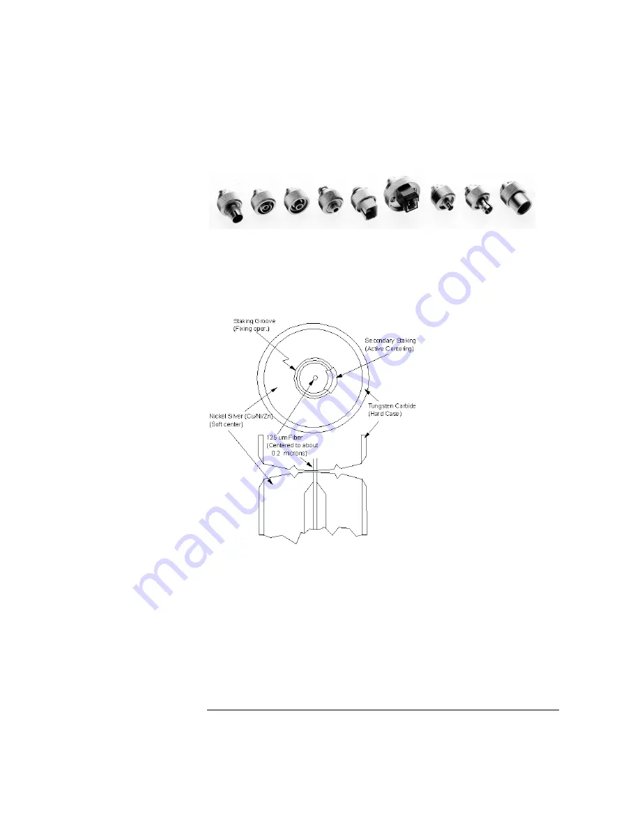
Figure 2-2. Universal adapters to Diamond HMS-10.

The HMS-10 encases the fiber within a soft nickel silver (Cu/Ni/Zn) center 
which is surrounded by a tough tungsten carbide casing, as shown in 

Figure 2-3

.

Figure 2-3. Cross-section of the Diamond HMS-10 connector.

The nickel silver allows an active centering process that permits the glass fiber 
to be moved to the desired position. This process first stakes the soft nickel 
silver to fix the fiber in a near-center location, then uses a post-active staking 
to shift the fiber into the desired position within 0.2

µ

m. This process, plus the 

keyed axis, allows very precise core-to-core alignments. This connector is 
found on most Agilent Technologies lightwave instruments.

Summary of Contents for 83437A

Page 1: ...Agilent 83438A Erbium ASE Source User s Guide ...

Page 2: ...to defects resulting from improper or inadequate maintenance by Buyer Buyer supplied software or interfac ing unauthorized modifica tion or misuse operation outside of the environmental specifications for the product or improper site preparation or maintenance No other warranty is expressed or implied Agilent Technologies specifically dis claims the implied warranties of merchantability and fitnes...

Page 3: ...de output orig inates from the amplified spontaneous emission ASE of an Erbium doped fiber amplifier The power spectral density of the output is up to one hundred times 20 dB greater than that of edge emitting LEDs for example the Agilent 83437A Broadband Light Source and up to 100 000 times 50 dB greater than white light tungsten lamp sources An internal optical isolator protects the Agilent 8343...

Page 4: ...nnector is no excep tion When you use improper cleaning and handling techniques you risk expensive instrument repairs damaged cables and compromised measurements Before you connect any fiber optic cable to the Agilent 83438A refer to Cleaning Con nections for Accurate Measurements on page 2 11 Laser classification The Agilent 83438A is classified as an IEC LASER Class 1 The total power of light en...

Page 5: ...v The Agilent 83438A At a Glance Rear view of instrument ...

Page 6: ...se parts Do not attempt to clean internally WAR N I N G This is a Safety Class 1 product provided with a protective earthing ground incorporated in the power cord The mains plug shall only be inserted in a socket outlet provided with a protective earth contact Any interruption of the protective conductor inside or outside of the product is likely to make the product dangerous Intentional interrupt...

Page 7: ... ambient temperature outside the cabinet must be less than the maximum operating temperature of the product by 4 C for every 100 watts dissipated in the cabinet If the total power dissipated in the cabinet is greater than 800 watts then forced convection must be used C AUT IO N Always use the three prong ac power cord supplied with this instrument Failure to ensure adequate earth grounding by not ...

Page 8: ......

Page 9: ...ression 2 7 Modulating the Output Light 2 10 Cleaning Connections for Accurate Measurements 2 11 3 Specifications and Regulatory Information Specifications 3 3 Regulatory Information 3 6 4 Reference Instrument Options 4 2 Accessories 4 2 Front Panel Fiber Optic Adapters 4 3 Power Cords 4 4 Agilent Technologies Service Offices 4 5 5 Servicing General Information 5 4 Electrostatic Discharge Informat...

Page 10: ......

Page 11: ...1 Step 1 Inspect the Shipment 1 4 Step 2 Check the Fuse 1 5 Step 3 Connect the Line Power Cable 1 6 Step 4 Turn on the Agilent 83438A 1 7 Returning the Instrument for Service 1 8 Getting Started ...

Page 12: ...rovided with a protective earth contact Any interruption of the protective conductor inside or outside of the product is likely to make the product dangerous Intentional interruption is prohibited C AUT IO N This product has autoranging line voltage input Be sure the supply voltage is within the specified range C AUT IO N VENTILATION REQUIREMENTS When installing the product in a cabinet the convec...

Page 13: ...and accessories The Agilent 83438A s front panel OPTICAL OUT connector is no excep tion When you use improper cleaning and handling techniques you risk expensive instrument repairs damaged cables and compromised measurements Before you connect any fiber optic cable to the Agilent 83438A refer to Cleaning Con nections for Accurate Measurements on page 2 11 ...

Page 14: ...out waiting for a settlement from the transportation company Notify the Agilent Technologies customer engineer of any problems 2 Make sure that the serial number and options listed on the instrument s rear panel label match the serial number and options listed on the shipping document The following figure is an example of the rear panel serial number label Table 1 1 Agilent 83438A Options Option D...

Page 15: ...drawer 4 Verify that the value of the line voltage fuse in the pull out drawer is correct The recommended fuse is an IEC 127 5 20 mm 6 3A 250 V Agilent part number 2110 0703 Notice that an extra fuse is provided in a drawer located on the fuse holder WAR N I N G For continued protection against fire hazard replace line fuse only with same type and ratings type T 6 3A 250V for 100 240V operation Th...

Page 16: ...ify that the line power meets the requirements shown in the following table 2 Connect the line power cord to the instrument s rear panel connector 3 Connect the other end of the line power cord to the power receptacle Various power cables are available to connect the Agilent 83438A to ac power outlets unique to specific geographic areas The cable appropriate for the area to which the Agilent 83438...

Page 17: ...nd before other parts of the instrument 2 Use the front panel ACTIVE key to turn the light output on and off If the Agilent 83438A fails to turn on properly consider the following possibili ties Is the line fuse good Does the line socket have power Is it plugged into the proper ac power source If the instrument still fails return it to Agilent Technologies for repair Refer to Returning the Instrum...

Page 18: ...enance contract it will be repaired under the terms of the warranty or contract the warranty is at the front of this manual If the instrument is no longer under warranty or is not covered by an Agilent Technologies mainte nance plan Agilent Technologies will notify you of the cost of the repair after examining the unit When an instrument is returned to a Agilent Technologies service office for ser...

Page 19: ... N Instrument damage can result from using packaging materials other than the original materials Never use styrene pellets as packaging material They do not adequately cushion the instrument or prevent it from shifting in the carton They may also cause instrument damage by generating static electricity 3 Pack the instrument in the original shipping containers Original materials are available throu...

Page 20: ... filled with air bubbles Use the pink antistatic Air Cap to reduce static electricity Wrapping the instrument several times in this ma terial will protect the instrument and prevent it from moving in the carton 4 Seal the carton with strong nylon adhesive tape 5 Mark the carton FRAGILE HANDLE WITH CARE 6 Retain copies of all shipping papers ...

Page 21: ...sponse Measurements 2 3 To characterize a passive device 2 5 Ambient Light Suppression 2 7 To suppress ambient light 2 8 Modulating the Output Light 2 10 Cleaning Connections for Accurate Measurements 2 11 Making Measurements ...

Page 22: ...This combination provides up to 70 dB of measurement range And because of the Agilent 83438A s rela tively high power density the optical spectrum analyzer can sweep much faster than if a white light source surface emitting LED or even an EELED were used The last section of this chapter explains how to maintain top performance of your instrument by using proper handling and cleaning techniques Be ...

Page 23: ...controller is used to characterize polarization dependencies of a device For example the center wavelength shift or the polarization dependent loss of a demultiplexer If your instrument has Option 009 installed it contains a built in polarizer Increasing wavelength accuracy When measuring deep notch filters increased absolute wavelength accuracy may be required To increase wavelength accuracy the ...

Page 24: ...2 4 Making Measurements Performing Stimulus Response Measurements ...

Page 25: ... the proper wavelength range 5 Press REF LEVEL and set the reference level to 10 dBm 6 Press SENS and set the sensitivity to 70 dBm You can increase the sensitivity beyond this value if needed 7 If you are measuring a deep notch filter more sensitivity may be required Perform the following steps a Press Amptd MORE and then CHOP On so that On is underlined b Press BW Swp SWPTIME AutoMan and set the...

Page 26: ... range or resolution bandwidth are made after this trace is stored repeat this step 10 Insert the device you are testing between the optical spectrum analyzer and the Agilent 83438A 11 Press NORMAL ON OFF to turn the marker on Rotate the front panel knob to read the values along the response ...

Page 27: ... 71450 1 2B optical spectrum analyzer can be used to eliminate this error In order to perform this measurement the Agilent 83438A s output is modu lated at 270 Hz Because the optical spectrum analyzer has the ability to syn chronize its data acquisition with the modulated light it can subtract out the effects of ambient light To learn more about using the optical spectrum ana lyzer s adc trigger f...

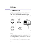
Page 28: ... power to the optical spectrum analyzer than the desired source 1 Connect the equipment as shown in the following figure 2 Set the square wave generator for a frequency of 270 Hz Set its voltage output to TTL levels The TTL low state is defined to be within 0 to 0 8 Vdc The TTL high state is defined to be within 2 0 to 5 Vdc If you use a different modulation frequency set the optical spectrum anal...

Page 29: ...nter 5 dB 7 Press MORE CHOP On Off so that Off is underlined 8 Press BW Swp SWPTIME AutoMan and set the sweep time to 10 seconds 9 Press MORE MORE adc trigger and then ADCTRIG AC 10 Press ADCTRIG DELAY and enter a value of 1 ms 11 The display should now show the proper amplitude values with the effect of the ambient light subtracted out ...

Page 30: ...ible signal Modulation rates can range from DC to 300 Hz A high TTL value turns the source on A low TTL value turns the source off The TTL low state is defined to be within 0 to 0 8 Vdc The TTL high state is defined to be within 2 0 to 5 Vdc The following schematic shows the input circuitry for the MODULATION INPUT connector If no signal is present on the MODULATION INPUT connector the source is t...

Page 31: ...ly in the mechanical assembly that holds the ferrule in position against another identical ferrule Connectors also vary in the polish curve and concentricity of the core within the cladding Mating one style of cable to another requires an adapter Agilent Technologies offers adapters for most instruments to allow testing with many different cables Figure 2 1 on page 2 12 shows the basic components ...

Page 32: ...epresents a good compromise between performance reli ability and cost If properly maintained and cleaned this connector can withstand many repeated connections However many instrument specifications require tighter tolerances than most connectors including the FC PC style can deliver These instruments cannot tolerate connectors with the large non concentricities of the fiber common with ceramic st...

Page 33: ...ection of the Diamond HMS 10 connector The nickel silver allows an active centering process that permits the glass fiber to be moved to the desired position This process first stakes the soft nickel silver to fix the fiber in a near center location then uses a post active staking to shift the fiber into the desired position within 0 2 µm This process plus the keyed axis allows very precise core to...

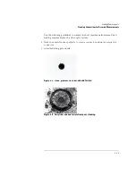
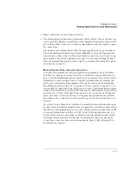
Page 34: ...he end of the fiber any stray particles or finger oil can have a significant effect on connector performance Where many repeat connections are required use of a connector saver or patch cable is recommended Figure 2 4 shows the end of a clean fiber optic cable The dark circle in the center of the micrograph is the fiber s 125 µm core and cladding which carries the light The surrounding area is the...

Page 35: ...hieve the best possible performance when making measurements on a fiber optic system Never use metal or sharp objects to clean a connector and never scrape the connector Avoid matching gel and oils Figure 2 4 Clean problem free fiber end and ferrule Figure 2 5 Dirty fiber end and ferrule from poor cleaning ...

Page 36: ...ber optic cable into a connector gently insert it in as straight a line as possible Tipping and inserting at an angle can scrape material off the inside of the connector or even break the inside sleeve of connectors made with ceramic material When inserting a fiber optic connector into a connector make sure that the fi ber end does not touch the outside of the mating connector or adapter Avoid ove...

Page 37: ...performance they can be used to determine connector degradation A smooth polished fiber end should pro duce a good return loss measurement The quality of the polish establishes the difference between the PC physical contact and the Super PC con nectors Most connectors today are physical contact which make glass to glass connections therefore it is critical that the area around the glass core be cl...

Page 38: ...e procedures in this section provide the proper steps for cleaning fiber optic cables and Agilent Technologies universal adapters The initial cleaning using the alcohol as a solvent gently removes any grit and oil If a caked on layer of material is still present this can happen if the beryllium copper sides of the ferrule retainer get scraped and deposited on the end of the fiber during insertion ...

Page 39: ...w clean lint free cotton swab or lens paper 4 Clean the fiber end with the swab or lens paper Do not scrub during this initial cleaning because grit can be caught in the swab and become a gouging element 5 Immediately dry the fiber end with a clean dry lint free cotton swab or lens paper 6 Blow across the connector end face from a distance of 6 to 8 inches using filtered dry compressed air Aim the...

Page 40: ... adapters allow you to connect the instrument to different types of fiber optic cables Figure 2 7 Universal adapters 1 Apply isopropyl alcohol to a clean foam swab Cotton swabs can be used as long as no cotton fibers remain after cleaning The foam swabs listed in this section s introduction are small enough to fit into adapters Although foam swabs can leave filmy deposits these deposits are very t...

Page 41: ...3 Specifications 3 3 Regulatory Information 3 6 Specifications and Regulatory Information ...

Page 42: ... All speci fications apply after the instrument s temperature has been stabilized after 15 minutes of continuous operation Characteristics provide useful information by giving functional but nonwar ranted performance parameters Characteristics are printed in italics Calibration cycle This instrument requires periodic verification of performance The instrument should have a complete verification of...

Page 43: ...rature change 1 C measured with power meter having 30 dB return loss and after one hour warm up time General Characteristics Spectral density 1530 nm 1550 nm 1560 nm 13 dBm 1 nm 50 µW nm 16 dBm 1 nm 25µW nm Option 009 13 dBm 1 nm 50 µW nm 16 dBm 1 nm 25µW nm Option 009 13 dBm 1 nm 50 µW nm 16 dBm 1 nm 25µW nm Option 009 Output return loss 30 dB characteristic 50 dB characteristic a Degree of polar...

Page 44: ...3 4 Specifications and Regulatory Information Specifications Characteristic output spectrum 1500 nm to 1600 nm Characteristic output spectrum 1550 nm to 1560 nm ...

Page 45: ...ency nominals 50 Hz 60 Hz range 47 63 Hz Altitude Up to 15 000 feet 4 572 meters Operating temperature 0 C to 45 C Storage temperature 40 C to 70 C Maximum relative humidity 80 for temperatures up to 31 C decreasing linearly to 50 relative humidity at 40 C Laser Classification FDA Laser Class I according to 21 CFR 1040 10 IEC Laser 1 according to IEC 60825 Weight 5 5 kg 12 lb Dimensions H x W x D ...

Page 46: ...TALLATION CATEGORY II and POLLU TION DEGREE 2 per IEC 1010 and 664 respectively Notice for Germany Noise Declaration This is to declare that this instrument is in conformance with the German Reg ulation on Noise Declaration for Machines Laermangabe nach der Maschinen laermrerordnumg 3 GSGV Deutschland Acoustic Noise Emission Geraeuschemission LpA 70 dB Operator position Normal position per ISO 777...

Page 47: ...3 7 Specifications and Regulatory Information Regulatory Information Declaration of Conformity I ll ...

Page 48: ......

Page 49: ...4 Instrument Options 4 2 Accessories 4 2 Front Panel Fiber Optic Adapters 4 3 Power Cords 4 4 Agilent Technologies Service Offices 4 5 Reference ...

Page 50: ... 81113PC DIN 4108 angled to Super PC straight patchcord for use with Option 022 and Option 013 instruments Option Description 009 Built in polarizer 011 Diamond HMS 10 fiber optic input connector interface 013 DIN 47256 fiber optic input connector interface 014 ST fiber optic input connector interface 017 SC fiber optic input connector interface 022 Angled contact fiber optic output interface ...

Page 51: ...lent Part Number Diamond HMS 10 81000AI FC PCa a The FC PC adapter is the standard adapter supplied with the instrument 81000FI D4 81000GI SC 81000KI DIN 81000SI ST 81000VI Biconic 81000WI Dust Covers FC connector 1005 0594 Diamond HMS 10 connector 1005 0593 DIN connector 1005 0595 ST connector 1005 0596 SC connector 1005 0597 ...

Page 52: ... nations 125V 8120 1378 8120 1521 8120 1992 Straight NEMA5 15P 90 Straight Medical UL544 90 228 90 228 96 244 Jade Gray Jade Gray Black United States Canada Mexico Philippines Taiwan 250V 8120 2104 8120 2296 Straight SEV1011 1959 24507 Type 12 90 79 200 79 200 Mint Gray Mint Gray Switzerland 220V 8120 2956 8120 2957 Straight DHCK107 90 79 200 79 200 Mint Gray Mint Gray Denmark 250V 8120 4211 8120 ...

Page 53: ...ers listed below Agilent Technologies Service Numbers Austria 01 25125 7171 Belgium 32 2 778 37 71 Brazil 11 7297 8600 China 86 10 6261 3819 Denmark 45 99 12 88 Finland 358 10 855 2360 France 01 69 82 66 66 Germany 0180 524 6330 India 080 34 35788 Italy 39 02 9212 2701 Ireland 01 615 8222 Japan 81 426 56 7832 Korea 82 2 3770 0419 Mexico 5 258 4826 Netherlands 020 547 6463 Norway 22 73 57 59 Russia...

Page 54: ......

Page 55: ...eck the line power fuse 5 19 Performance Tests 5 20 Test 1 Total Output Power 5 21 Test 2 Power Stability 5 22 Adjustment Procedure 5 23 To adjust total power 5 24 Replacing Instrument Assemblies 5 26 To remove the instrument cover 5 27 To replace the A2 Source assembly 5 28 To replace the A5 Laser Driver Board Assembly 5 30 To route the rear panel BNC modulation cable 5 32 To replace line filter ...

Page 56: ... G These servicing instructions are for use by qualified personnel only To avoid electrical shock do not perform any servicing unless you are qualified to do so WAR N I N G The opening of covers or removal of parts is likely to expose dangerous voltages Disconnect the instrument from all voltage sources while it is being opened WAR N I N G The power cord is connected to internal capacitors that ma...

Page 57: ...place line fuse only with same type and ratings type T 6 3A 250V for 100 240V operation The use of other fuses or materials is prohibited WAR N I N G Use of controls or adjustment or performance of procedures other than those specified herein may result in hazardous radiation exposure ...

Page 58: ... assemblies should be performed at a static safe work station Refer to Electrostatic Discharge Information on page 5 10 for more information on preventing ESD A2 ASE Source Assembly The A2 ASE Source Assembly can not be repaired It must be returned to Agi lent Technologies for service as a complete unit The following assemblies are included in the A2 ASE Source Assembly Refer to Major Assemblies o...

Page 59: ...aser A2A3 to the A2A1 assembly Other laser paths outside of the A2A1 assembly do not require precautions to maintain safety Table 5 1 Internal Labels This label warns you that removing the A2A1 Fiber Track Assembly s cover exposes the path of a CLASS IIIb LASER PRODUCT Never remove this cover This label identifies the A2A1 Fiber Track Assembly The serial and option numbers listed on the label are ...

Page 60: ...able 5 3 Major Assemblies Reference Designator Description A1 Keyboard Assembly A2 ASE Source Assembly Not orderable return A2 to Agilent Technologies A2A1 Fiber Track Assembly Not orderable return A2 to Agilent Technologies A2A2 Laser Modulation Board Assembly A2A3 Pump laser Not orderable return A2 to Agilent Technologies A3 Power Distribution Board Assembly A4 Power Supply Board Assembly A5 Las...

Page 61: ...5 7 Servicing General Information ...

Page 62: ...3 A3J7 to B1 Part of B1 W4 Power supply cable A2A2J2 pin 5 to front panel LINE LED indicator green wire W5 Power supply cable A2A2J1 to front panel ACTIVE LED and A1 assembly W6 Power distribution cable A4J2 to A3J6 W7 Modulation cable A3J5 to A2A2J2 W8 Driver 1 cable A3J1 to A5J2 W9 W11 Not assigned W12 Ribbon cable A2A2J91 to A5J1 W13 W16 Not assigned W17 SMB to BNC cable rear panel J1 to A2A2J2...

Page 63: ...5 9 Servicing General Information ...

Page 64: ...d at a static safe work station The following figure shows an example of a static safe work station using two types of ESD protection Conductive table mat and wrist strap combination Conductive floor mat and heel strap combination Both types when used together provide a significant level of ESD protection Of the two only the table mat and wrist strap combination provides adequate ESD protection wh...

Page 65: ... when working on circuitry with a voltage potential greater than 500 volts Table 5 5 Static Safe Accessories Agilent Part Number Description 9300 0797 3M static control mat 0 6 m 1 2 m 2 ft 4 ft and 4 6 cm 15 ft ground wire The wrist strap and wrist strap cord are not included They must be ordered separately 9300 0980 Wrist strap cord 1 5 m 5 ft 9300 1383 Wrist strap color black stainless steel wi...

Page 66: ...5 17 To check the A4 Power Supply Board Assembly 5 18 To check the line power fuse 5 19 WAR N I N G To avoid exposure to the laser path of a CLASS IIIb LASER PRODUCT do not open the A2A1 assembly There are no serviceable components inside Do not damage the fiber optic cable that connects the CLASS IIIb pump laser A2A3 to the A2A1 assembly Other laser paths outside of the A2A1 assembly do not requi...

Page 67: ... of parts is likely to expose dangerous voltages Disconnect the instrument from all voltage sources while it is being opened WAR N I N G The power cord is connected to internal capacitors that may remain live for five seconds after disconnecting the plug from its power supply ...

Page 68: ...ctor Modulation reduces the average output power Of course the de crease in power is tied to the duty cycle of the modulating signal Check the rear panel MODULATION INPUT connector If a BNC short is con nected the output is turned off 2 Perform the adjustment procedure To adjust total power on page 5 24 Confirm that the power is low and cannot be adjusted within the specification 3 Perform the pro...

Page 69: ...er procedure to replace the A5 assembly could destroy the laser or result in increased laser output power from the front panel OPTICAL OUT connector Increased laser output power may change the laser classification of the product 1 Remove the power supply cable from J2 on the A5 Laser Driver Board Assembly The end of this cable can be probed to measure all of the dc voltages supplied in the assembl...

Page 70: ... driving the pump laser is operating correctly If the yellow LED is on the pump laser s temperature stabilization loop is not functioning the current to the pump laser is automatically turned off which turns the green LED off 4 If the yellow LED is off check ribbon cable W12 ...

Page 71: ...large 3W black resistor on the assembly that is closest to the pump laser 4 Measure the voltage on the end of the resistor that is furthest from the pump laser The voltage should measure approximately 1V to 2V 5 The pump laser is being driven by the current source and should be turned on 6 Press the front panel ACTIVE key so that the front panel ACTIVE light is turned off The voltage measured at t...

Page 72: ...all of the dc voltages supplied in the instrument The following list shows each wire color its color code and its purpose Red 2 wire 15V White red 92 wire 5V Violet 7 wire 15V Black 0 wire ground White black 90 wire ground 3 If no voltages are detected check that the ac line input voltage at the cable that connects to J1 on the A4 Power Supply Board Assembly Measure the line voltage across the whi...

Page 73: ...river to open the pull out fuse drawer The recommended fuse is an IEC 127 5 20 mm 6 3A 250 V Agilent Technol ogies part number 2110 0703 Notice that an extra fuse is provided in a drawer located on the fuse holder WAR N I N G For continued protection against fire hazard replace line fuse only with same type and ratings type T 6 3A 250V for 100 240V operation The use of other fuses or materials is ...

Page 74: ...ing any of the performance tests Test 1 Total Output Power 5 21 Test 2 Power Stability 5 22 Calibration Cycle This instrument requires periodic verification of performance The instrument should have a complete verification of specifications at least once every two years C AUT IO N Option 022 instruments have an angled fiber output Be sure to use an angled fiber patchcord during testing If you do n...

Page 75: ...e Tests Test 1 Total Output Power Description Total power is verified using the following devices Power meter Procedure 1 Connect a power meter to the Agilent 83438A s front panel OPTICAL OUT connector 2 Measure the total power ...

Page 76: ...T connector 3 Remove any BNC termination on the rear panel MODULATION INPUT connector 4 Configure the power meter to measure total drift in output power over 15 minutes Start the test 5 After 15 minutes have passed the total output power should not have drifted more than 0 02 dB Record the maximum drift on the following line Maximum drift 15 minutes ____________ dB 6 Configure the power meter to m...

Page 77: ...vailable you can purchase the required accessories from Agilent Technologies These include the Agilent 81000SI DIN connector interface and the Agilent 81113PC DIN 4108 angled to Super PC patchcord WAR N I N G To avoid exposure to the laser path of a CLASS IIIb LASER PRODUCT do not open the A2A1 assembly There are no serviceable components inside Do not damage the fiber optic cable that connects th...

Page 78: ...Assembly Procedure 1 Remove the instrument s top and bottom covers 2 Connect a power meter to the Agilent 83438A s front panel OPTICAL OUT connector 3 Locate R18 on the A5 Laser driver board assembly for the pump laser See the following figure 4 Adjust potentiometer R18 on the A5 Laser driver board assembly to set the output power between 5 5 dBm and 8 1 dBm 3 6 mW to 6 5 mW ...

Page 79: ...5 25 Servicing Adjustment Procedure ...

Page 80: ...ove and replace the major instrument assemblies These include the following procedures To remove the instrument cover 5 27 To replace the A2 Source assembly 5 28 To replace the A5 Laser Driver Board Assembly 5 30 To route the rear panel BNC modulation cable 5 32 To replace line filter assembly FL1 5 33 To replace a cable clip 5 34 ...

Page 81: ...king at the rear panel 3 Use a T 15 TORX driver to back out the screw that attaches the top cover to the instrument Note that the screw is permanently secured to the cover 4 After the screw is backed out slide the cover toward the rear of the instrument to remove it 5 Remove the bottom cover using the same technique as used for the top cover 6 Remove the two side covers ...

Page 82: ...ly Other laser paths outside of the A2A1 assembly do not require precautions to maintain safety 1 Remove the instrument s top bottom and right side covers 2 Remove all cables attached to the A2A2 Laser Modulation Board Assembly 3 Remove the trim strip located on the top of the front frame 4 Use a T 10 TORX driver to remove the six screws that secure the front panel to the front frame They are loca...

Page 83: ... T 10 TORX driver to remove the four screws securing the A2 assembly to the instrument s right side frame 8 Place the instrument on it s right side 9 Use a T 10 TORX driver to remove the three screws securing the A2 assembly to the bottom of the instrument s main deck sheet metal assembly 10 Remove the A2 assembly ...

Page 84: ...sed laser output power may change the laser classification of the product 1 Remove the A5 Laser Driver Board Assembly from the instrument 2 Locate resistors R2 R8 and R9 as shown on the following diagram 3 Read the values of each of these three resistors and write them down The values should be printed on the sides of each resistor The possible values of each of resistors is 82Ω 100Ω 125Ω or 150Ω ...

Page 85: ...5 31 Servicing Replacing Instrument Assemblies Location of resistors R2 R8 and R9 ...

Page 86: ...5 32 Servicing Replacing Instrument Assemblies To route the rear panel BNC modulation cable The figure below shows the correct path for the rear panel BNC cable Be sure to route this cable as shown ...

Page 87: ...ws Over tightening these screws will damage the line filter s flange Observe the following warning about correct wire attachment The wire color codes in the figure refer to the following cable colors 54 green yellow 98 white gray 918 white brown gray WAR N I N G Be sure to solder the wires to FL1 in the correct positions as shown in the following figure Failure to attach these wires correctly coul...

Page 88: ...roughout the instrument to attach cables to sheet metal housings They attach with self adhesive bonds 1 Remove the old clip 2 Remove any remaining glue 3 Clean the surface using isopropyl alcohol 4 Remove the paper backing from the bottom of the new clip 5 Press the clip firmly onto the surface ...

Page 89: ...nstrument Cover Parts on page 5 48 Part ordering information To order an assembly or mechanical part quote the Agilent Technologies part number and indicate the quantity required To order a part that is not listed include the following information with the order Agilent 83438A model number Instrument serial number Description of where the part is located what it looks like and its function if know...

Page 90: ...red through a local Agilent Technologies office when the orders require billing and invoicing Prepaid transportation There is a small handling charge for each order No invoices To provide these advantages a check or money order must accompany each order Mail order forms and specific ordering information are available through your local Agilent Technologies office Direct phone order system The toll...

Page 91: ...es A2A1 Fiber Track Assembly Not orderable return A2 to Agilent Technologies A2A2 Laser Modulation Board Assembly Not orderable return A2 to Agilent Technologies A2A3 Pump laser A3 83437 60012 Power Distribution Board Assembly A4 0950 2293 Power Supply Board Assembly A5 83438 60004 Laser Driver Board Assembly includes packet of resistors B1 83437 20006 Fan Assembly FL1 9135 0270 Line Module Filter...

Page 92: ...5 38 Servicing Replaceable Parts ...

Page 93: ...J2 pin 5 to front panel LINE LED indicator green wire W5 83437 60004 Power supply cable A2A2J1 to front panel ACTIVE LED and A1 assembly W6 83437 60001 Power distribution cable A4J2 to A3J6 W7 83437 60002 Modulation cable A3J5 to A2A2J2 W8 83437 60013 Driver cable 11 inches long A3J1 to A5J2 W9 W11 Not assigned W12 83437 60020 Ribbon cable A2A2J91 to A5J1 W13 W16 Not assigned W17 8120 5056 SMB to ...

Page 94: ...5 40 Servicing Replaceable Parts ...

Page 95: ...ximum 6 85680 40004 2 LED mount 7 83437 20004 1 LED spacer 8 83410 20003 1 Adapter 9 0515 0430 3 Screw with washer TORX T10 Pan Head M3 X 0 5 6 mm long 10 0535 0042 3 Nut hex PLSTC LKG M3 X 0 5 11 1400 0755 3 Component clip 0 75 in x 0 75 in 12 1400 0249 1 Cable tie wrap 13 0380 0019 2 Spacer round 0 188 IN LNG 14 0590 0106 2 Nut hex PLSTC LKG 2 56 THD 15 3050 0891 2 Washer flat M3 0 3 3 mm inner ...

Page 96: ...5 42 Servicing Replaceable Parts ...

Page 97: ...E IEC 4 0515 2032 2 Screw TORX T10 Flat Head M3 X 0 5 8 mm long 5 0535 0033 4 Nut hex M3 5 X 0 6 6 2190 0585 4 Washer flat HLLC 3 6 mm inside diameter 7 3050 0892 4 Washer flat MTLC 3 8 mm inside diameter 8 2950 0035 4 Nut hex 15 32 32 9 2190 0102 4 Washer lock 0 472 inside diameter 10 6960 0002 3 Hole plug for 0 5 inner diameter hole 11 0515 0372 4 Screw TORX T10 Pan Head M3 x 0 5 8 mm long ...

Page 98: ...5 44 Servicing Replaceable Parts ...

Page 99: ...hield for A4 Power Supply 7 1400 0755 2 Component clip 0 75 in x 0 75 in 8 1400 0249 1 Cable tie wrap 9 1 A2MP1 LED heat sink part of A2 assembly 10 1 Fiber container lid part of A2 assembly not separately orderable 11 1 Fiber container part of A2 assembly not separately orderable 12 1 Fiber track part of A2 assembly not separately orderable 13 0515 0830 2 Screw TORX T10 Pan Head M3 x 0 5 28 mm lo...

Page 100: ...5 46 Servicing Replaceable Parts ...

Page 101: ...2 Side frame 2 5001 0538 2 Trim strip side not shown 3 0515 0458 10 Screw TORX T10 Pan Head M3 5 x 0 6 8 mm long 4 0515 2086 8 Screw TORX T15 Flat Head M4 x 0 7 7 mm long 5 0515 0377 4 Screw TORX T10 Pan Head M3 5 x 0 6 10 mm long 6 1400 0249 1 Cable tie wrap 7 5 Screw part of A2 assembly not separately orderable ...

Page 102: ...laceable Parts Table 5 12 Instrument Cover Parts Item Agilent Part Number Qty Description 5062 3730 1 Cover top 5062 3742 1 Cover bottom 5062 3751 1 Cover left side 83437 00009 1 Cover right side 5041 8801 4 Molded feet ...

Page 103: ...er 3 6 cleaning adapters 2 20 cabinet vi 1 2 fiber optic connections 2 11 2 19 non lensed connectors 2 19 compressed dust remover 2 18 connector care 2 11 correction factors 2 3 cotton swabs 2 18 crosstalk 2 3 D damaged shipment 1 4 declaration of conformity 3 7 deep notch filters 2 3 digital modulation 2 10 dimensions of instrument 3 5 dust caps 2 19 DWDM 2 3 E edge emitting LED iii ESD electrost...

Page 104: ...1 4 ordering parts 5 35 P packaging for shipment 1 9 parts bottom of instrument 5 48 cables 5 39 major assemblies 5 6 5 37 ordering 5 35 replacing 5 26 5 35 side of instrument 5 47 top of instrument 5 41 5 43 5 45 performance tests 5 20 polarization 2 3 product notes 2 7 R rack mounting requirements 1 2 radiation exposure iv rear panel labels v MODULATION INPUT connector 2 10 regulatory informatio...

Page 105: ...Index 3 Index T tools for servicing 5 4 troubleshooting 5 2 TTL logic 2 10 turning output off 2 10 V ventilation requirements 1 2 W wavelength accuracy 2 3 specifications 3 3 weight 3 5 ...

Page 106: ......
Reviews: