8510XF Network Analyzer Systems 3-47
Operation
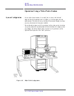
Operation Using a Wafer Probe Station
Available Equipment
Agilent Technologies does not manufacture or supply a probe station for the
8510XF. The recommended supplier of probe stations is:
Cascade Microtech, Inc.
2430 NW 206th Ave., Beaverton, Oregon 97006, USA
Telephone: (503) 601-1000
Fax: (503) 601-1002
Japan: (03) 5478-6105
Europe: +44 (0) 1295-812828
E-mail: sales@cmicro.com
Web site: www.cascademicrotech.com
In addition to probe stations, Cascade offers a variety of accessories that are
compatible with the 8510XF (including positioners, wafer test probes,
calibration substrates, and calibration software).
Device Connections
Each test port of the 8510XF is connected to a wafer test probe (through a
1.0 mm coaxial cable, or through an adapter and another type of coaxial
cable). Contact the manufacturer of the wafer probe station and an Agilent
office for information on the cables and adapters needed to connect the test
heads to the wafer probe station (refer to
“Contacting Agilent” on page -v
The probe tips make direct contact with the on-wafer devices to be
measured.
Positioners on the probe station adjust the position of the probe tips, in three
axes of movement: left-right motions along the X axis, forward-back
motions along the Y axis, and up-down motions along the Z axis. Motion in
the Z-axis is typically controlled by a micropositioner to which the wafer
probe (but not the test head) is attached.
In order to measure an on-wafer device, you will maneuver the probe tip into
a position directly above the device, and then bring the tip down to contact
the substrate. A microscope mounted on the probe station provides a
close-up view of this process.
Types of Probe
Stations
Probe stations are classified as manual, semi-automatic, and fully automatic.
•
A manual probe station requires the operator to make all position
adjustments manually, using a microscope to watch the position of the
probe tips.
•
Semi-automatic probe stations can be programmed with a wafer map, so
that the system automatically locates and measures every device on the
wafer. (Or, in “indexing” mode, the system measures the first device,
and waits for the operator to push a button before it proceeds to the next
device.)
•
Fully automatic probe stations are able to load a series of wafers from a
cassette, automatically measuring each DUT on each wafer (using a
wafer map) before replacing the wafer in the cassette.
Summary of Contents for 8510XF
Page 11: ...8510XF Network Analyzer Systems xi Compliance with Standards ...
Page 12: ...xii 8510XF Network Analyzer Systems Compliance with Standards ...
Page 136: ...4 18 8510XF Network Analyzer Systems Performance Verification CW Frequency Accuracy Test ...
Page 160: ...5 24 8510XF Network Analyzer Systems System Maintenance System Block Diagrams ...
Page 162: ...5 26 8510XF Network Analyzer Systems System Maintenance System Block Diagrams ...
Page 164: ...5 28 8510XF Network Analyzer Systems System Maintenance System Block Diagrams ...
Page 168: ...5 32 8510XF Network Analyzer Systems System Maintenance System Block Diagrams ...
Page 170: ...5 34 8510XF Network Analyzer Systems System Maintenance System Block Diagrams ...
Page 172: ...5 36 8510XF Network Analyzer Systems System Maintenance System Block Diagrams ...
Page 176: ...5 40 8510XF Network Analyzer Systems System Maintenance Troubleshooting ...
Page 188: ...6 12 8510XF Network Analyzer Systems Replaceable Parts Millimeter Wave Controller ...
Page 191: ...R ...
Page 192: ...R ...
Page 193: ...R ...
Page 194: ...R ...
Page 195: ...R ...
Page 196: ...R ...
Page 197: ...R ...
Page 198: ...HP E7350 calmckit cdr Rev 1 3 10 98 Menu Maps Cal Modify Cal Kit 7 17 7 18 ...
Page 199: ...R ...
Page 200: ...R ...
Page 201: ......
Page 202: ...R ...
Page 203: ...R ...
Page 204: ...R ...
Page 205: ...R ...
Page 206: ...R ...
Page 207: ...R ...
Page 208: ...R ...
Page 209: ...R ...
Page 210: ...R ...


