8510XF Network Analyzer Systems 5-7
System Maintenance
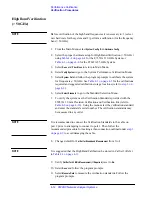
Detector Gain Calibration
Procedure
The calibration process consists of running a firmware routine that is internal
to the 8510XF; no external test equipment is required.
1. Be aware that the detector gain calibration process causes some 8510C
settings to change, and that the settings are not restored to their original
conditions afterward. If you want to return to the present settings, save
them before running the calibration.
2. Disconnect any devices from the test ports. During the calibration, the
8510XF will step through its entire power range; any device connected
to the test ports could be at risk of damage from excessive RF input
levels.
3. Call up the detector gain calibration menu by pressing:
[SYSTEM] {MORE} {RF POWER CONFIG} {MORE} {RESET DET GAIN CAL}
4. Choose one of the options from the menu:
a.
If
{RUN CAL + USER PRST}
is selected, the detector gain calibration
routine is run, and is followed by a user preset. This returns the
system to instrument state #8, and is the recommended option.
b.
If
{RUN CAL + FACT PRST}
is selected, the detector gain calibration
routine is run, and is followed by a factory preset.
c.
If
{RUN CAL NO PRESET}
is selected, the detector gain calibration
routine is run, but is not followed by a preset.
5. The calibration run takes about a minute, after which the system returns
to normal operation.
Summary of Contents for 8510XF
Page 11: ...8510XF Network Analyzer Systems xi Compliance with Standards ...
Page 12: ...xii 8510XF Network Analyzer Systems Compliance with Standards ...
Page 136: ...4 18 8510XF Network Analyzer Systems Performance Verification CW Frequency Accuracy Test ...
Page 160: ...5 24 8510XF Network Analyzer Systems System Maintenance System Block Diagrams ...
Page 162: ...5 26 8510XF Network Analyzer Systems System Maintenance System Block Diagrams ...
Page 164: ...5 28 8510XF Network Analyzer Systems System Maintenance System Block Diagrams ...
Page 168: ...5 32 8510XF Network Analyzer Systems System Maintenance System Block Diagrams ...
Page 170: ...5 34 8510XF Network Analyzer Systems System Maintenance System Block Diagrams ...
Page 172: ...5 36 8510XF Network Analyzer Systems System Maintenance System Block Diagrams ...
Page 176: ...5 40 8510XF Network Analyzer Systems System Maintenance Troubleshooting ...
Page 188: ...6 12 8510XF Network Analyzer Systems Replaceable Parts Millimeter Wave Controller ...
Page 191: ...R ...
Page 192: ...R ...
Page 193: ...R ...
Page 194: ...R ...
Page 195: ...R ...
Page 196: ...R ...
Page 197: ...R ...
Page 198: ...HP E7350 calmckit cdr Rev 1 3 10 98 Menu Maps Cal Modify Cal Kit 7 17 7 18 ...
Page 199: ...R ...
Page 200: ...R ...
Page 201: ......
Page 202: ...R ...
Page 203: ...R ...
Page 204: ...R ...
Page 205: ...R ...
Page 206: ...R ...
Page 207: ...R ...
Page 208: ...R ...
Page 209: ...R ...
Page 210: ...R ...


