4-10
8510XF Network Analyzer Systems
Performance Verification
Verification Procedures
c.
To make the thru connection, gently slide the right test (port 2)
towards the left test head (port 1) a little bit at a time, while turning
the threaded ring on the left head test port connector by hand onto
the cable attached to the right test head. Do not use the threaded ring
on the test port connector to pull the cable into the connector. Repeat
this process until the cable is firmly seated into port 1, then make the
threaded ring barely finger tight. Finally use the torque wrench on
the port 1 threaded ring and a backup wrench on the cable to tighten
the connection.
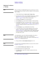
4. Select
Select Standard
to go to the Standard Selection Menu.
5. To verify the system use the Verification Standards provided with the
85059A 1.0 mm Precision Calibration and Verification Kit (refer to
). Using the menu select the verification standard and enter the
standard’s serial number. The verification standards may be measured in
any order.
NOTE
It is recommended to connect the Verification Standards to the cable on
port 2 prior to attempting to connect to port 1. Then follow the
recommended procedure for making a thru connection outlined under
above to avoid damaging the cable.
6. Use defaults for
Cal Set for Broadband Measurement: 1
and
Cal Set for 45 MHz
Measurement (If Required): 2
in the Standard Menu.
7. If your system has Option 005, verify that
Cal Set for 45 MHz Measurement (If
Required)
is set to
Yes
. Otherwise, set to
No
.
8. Select
Done
and follow the program prompts.
9. Select
Measure Data
to measure the verification standards. Follow the
program prompts.
10. When verification has been completed view the data, then print or save
(if required). If needed the verification standard can be remeasured by
selecting
Repeat Measure
.
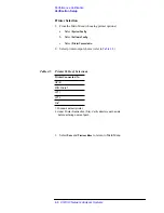
Table 4-6
Verification Standards from 1.0 mm Calibration and Verification Kit
Type of Standard
Part Number
Mismatched Thru Adapter
85059-60016
Match Thru Adapter
85059-60017
Summary of Contents for 8510XF
Page 11: ...8510XF Network Analyzer Systems xi Compliance with Standards ...
Page 12: ...xii 8510XF Network Analyzer Systems Compliance with Standards ...
Page 136: ...4 18 8510XF Network Analyzer Systems Performance Verification CW Frequency Accuracy Test ...
Page 160: ...5 24 8510XF Network Analyzer Systems System Maintenance System Block Diagrams ...
Page 162: ...5 26 8510XF Network Analyzer Systems System Maintenance System Block Diagrams ...
Page 164: ...5 28 8510XF Network Analyzer Systems System Maintenance System Block Diagrams ...
Page 168: ...5 32 8510XF Network Analyzer Systems System Maintenance System Block Diagrams ...
Page 170: ...5 34 8510XF Network Analyzer Systems System Maintenance System Block Diagrams ...
Page 172: ...5 36 8510XF Network Analyzer Systems System Maintenance System Block Diagrams ...
Page 176: ...5 40 8510XF Network Analyzer Systems System Maintenance Troubleshooting ...
Page 188: ...6 12 8510XF Network Analyzer Systems Replaceable Parts Millimeter Wave Controller ...
Page 191: ...R ...
Page 192: ...R ...
Page 193: ...R ...
Page 194: ...R ...
Page 195: ...R ...
Page 196: ...R ...
Page 197: ...R ...
Page 198: ...HP E7350 calmckit cdr Rev 1 3 10 98 Menu Maps Cal Modify Cal Kit 7 17 7 18 ...
Page 199: ...R ...
Page 200: ...R ...
Page 201: ......
Page 202: ...R ...
Page 203: ...R ...
Page 204: ...R ...
Page 205: ...R ...
Page 206: ...R ...
Page 207: ...R ...
Page 208: ...R ...
Page 209: ...R ...
Page 210: ...R ...


