5-6
8510XF Network Analyzer Systems
System Maintenance
Detector Gain Calibration
Detector Gain Calibration
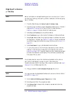
Purpose of the
Calibration
This is the first of two calibrations which, in combination, insure the
accuracy of absolute power levels at the test ports (the other is conversion
loss calibration, which is described on
The level control system includes a programmable gain circuit, which uses
step attenuators to adjust the level of the detector feedback signal, in .5 dB
steps. To compensate for imprecision in these attenuation steps, correction
factors must be applied to the programmable gain circuit.
Detector gain calibration is the process by which these correction factors are
gathered. For more information, see
“The Leveling Loop” on page 5-15
, and
“Level Calibration” on page 5-18
The Calibration
Process
During detector gain calibration, the 8510XF measures the effect of every
possible gain setting on the detector feedback level. Correction factors for
these gain settings are stored in an EEPROM within the millimeter-wave
controller.
The correction factors are taken at one fixed frequency, and then at another
fixed frequency. This process is automatic; the frequencies are specified in
firmware, and are chosen so as to give the level control system the greatest
possible dynamic range.
When to Calibrate
Running detector gain calibration takes about a minute. In choosing an
appropriate interval between calibrations, use the following guidelines:
•
For measurements in which absolute power levels are critical, perform
this calibration before every measurement calibration (see
•
If absolute power levels are not critical, you can perform this calibration
infrequently (on a monthly basis, for example).
•
If the controller or one of the test heads has been repaired or replaced,
perform this calibration before making measurements with the system.
•
If the 8510XF has been transported, or exposed to wide temperature
variations, perform this calibration before making measurements with
the system.
•
If the operating system firmware is reloaded, it is necessary to perform
the detector gain calibration.
Summary of Contents for 8510XF
Page 11: ...8510XF Network Analyzer Systems xi Compliance with Standards ...
Page 12: ...xii 8510XF Network Analyzer Systems Compliance with Standards ...
Page 136: ...4 18 8510XF Network Analyzer Systems Performance Verification CW Frequency Accuracy Test ...
Page 160: ...5 24 8510XF Network Analyzer Systems System Maintenance System Block Diagrams ...
Page 162: ...5 26 8510XF Network Analyzer Systems System Maintenance System Block Diagrams ...
Page 164: ...5 28 8510XF Network Analyzer Systems System Maintenance System Block Diagrams ...
Page 168: ...5 32 8510XF Network Analyzer Systems System Maintenance System Block Diagrams ...
Page 170: ...5 34 8510XF Network Analyzer Systems System Maintenance System Block Diagrams ...
Page 172: ...5 36 8510XF Network Analyzer Systems System Maintenance System Block Diagrams ...
Page 176: ...5 40 8510XF Network Analyzer Systems System Maintenance Troubleshooting ...
Page 188: ...6 12 8510XF Network Analyzer Systems Replaceable Parts Millimeter Wave Controller ...
Page 191: ...R ...
Page 192: ...R ...
Page 193: ...R ...
Page 194: ...R ...
Page 195: ...R ...
Page 196: ...R ...
Page 197: ...R ...
Page 198: ...HP E7350 calmckit cdr Rev 1 3 10 98 Menu Maps Cal Modify Cal Kit 7 17 7 18 ...
Page 199: ...R ...
Page 200: ...R ...
Page 201: ......
Page 202: ...R ...
Page 203: ...R ...
Page 204: ...R ...
Page 205: ...R ...
Page 206: ...R ...
Page 207: ...R ...
Page 208: ...R ...
Page 209: ...R ...
Page 210: ...R ...


