5-8 8510XF Network Analyzer Systems
System Maintenance
Conversion Loss Calibration
Conversion Loss Calibration
Purpose of the
Calibration
This is the second of the two calibrations that insure the accuracy of absolute
power levels at the test ports.
The RF-to-IF conversion loss of a mixer varies with frequency. To
compensate for these frequency-related variations, correction factors must
be applied to the level control system. Conversion loss calibration is the
process by which these correction factors are gathered.
(For more detail, see
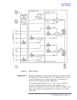
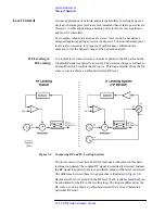
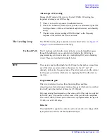
“The Leveling Loop” on page 5-15
“Level
The Calibration
Process
During conversion loss calibration, the test ports are monitored with a power
meter while the 8510XF steps through its frequency range. Based on the
measured power levels, correction factors for each frequency are stored in an
EEPROM within the millimeter-wave controller.
Measurement frequencies occur at intervals of 25 MHz, up to 18 GHz.
Above 18 GHz, measurement frequencies occur at intervals of 50 MHz.
When to Calibrate
Calibration is performed at the factory prior to shipment; thereafter it should
be performed as required.
NOTE
Conversion loss calibration data applies only to the specific combination of
controller and test heads calibrated together as a set. The cables connecting
the test heads to the controller also become part of the calibration. If the
controller or one of the test heads is repaired or replaced, the old calibration
data will no longer be valid.
Agilent Technologies
Customer Engineering
This calibration requires expensive test instruments, software and
accessories. For this reason, conversion loss calibration is to be performed
by an Agilent Technologies Customer Engineer or the factory only. Contact
your nearest Agilent Technologies office to order this service (refer to
Summary of Contents for 8510XF
Page 11: ...8510XF Network Analyzer Systems xi Compliance with Standards ...
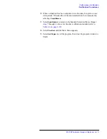
Page 12: ...xii 8510XF Network Analyzer Systems Compliance with Standards ...
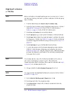
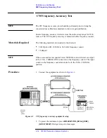
Page 136: ...4 18 8510XF Network Analyzer Systems Performance Verification CW Frequency Accuracy Test ...
Page 160: ...5 24 8510XF Network Analyzer Systems System Maintenance System Block Diagrams ...
Page 162: ...5 26 8510XF Network Analyzer Systems System Maintenance System Block Diagrams ...
Page 164: ...5 28 8510XF Network Analyzer Systems System Maintenance System Block Diagrams ...
Page 168: ...5 32 8510XF Network Analyzer Systems System Maintenance System Block Diagrams ...
Page 170: ...5 34 8510XF Network Analyzer Systems System Maintenance System Block Diagrams ...
Page 172: ...5 36 8510XF Network Analyzer Systems System Maintenance System Block Diagrams ...
Page 176: ...5 40 8510XF Network Analyzer Systems System Maintenance Troubleshooting ...
Page 188: ...6 12 8510XF Network Analyzer Systems Replaceable Parts Millimeter Wave Controller ...
Page 191: ...R ...
Page 192: ...R ...
Page 193: ...R ...
Page 194: ...R ...
Page 195: ...R ...
Page 196: ...R ...
Page 197: ...R ...
Page 198: ...HP E7350 calmckit cdr Rev 1 3 10 98 Menu Maps Cal Modify Cal Kit 7 17 7 18 ...
Page 199: ...R ...
Page 200: ...R ...
Page 201: ......
Page 202: ...R ...
Page 203: ...R ...
Page 204: ...R ...
Page 205: ...R ...
Page 206: ...R ...
Page 207: ...R ...
Page 208: ...R ...
Page 209: ...R ...
Page 210: ...R ...

