8510XF Network Analyzer Systems 5-15
System Maintenance
Theory of Operation
Advantages of IF leveling
Because the IF output of the mixer is fixed at 20 MHz, IF leveling has
important advantages over RF leveling:
•
There is no need for expensive broadband detectors.
•
The IF can be narrowly filtered, to keep noise to a minimum (typical RF
leveling schemes, which use broadband coupler/detectors, are inherently
noisy).
•
The detector is always reading a 20 MHz signal, so the frequency
response of the detector itself is not an issue.
The Leveling Loop
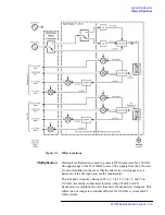
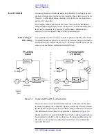
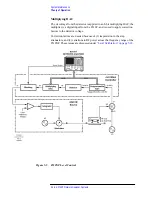
The 8510XF leveling loop is described in more detail below (see
for an illustration of the loop).
Feedback Path
The IF feedback path from the mixer to the level-control amplifier passes
through the millimeter-wave controller, and includes the following: a
programmable gain circuit, a detector, a multiplying DAC, and a blanking
circuit. These are described individually below.
NOTE
There is only one feedback path, but the IF input to that path can come from
any of the reference mixers (that is, the mixers for the “a1” and “a2”
channels, in the active frequency range). The active test port, and the current
test frequency, determine which mixer is supplying the IF feedback at any
one time.
Programmable gain
This circuit includes, in series, three fixed amplifiers and three
step-attenuators. Each attenuator includes three pads which can be switched
into the IF path (the smallest of these is a 0.5 dB pad).
By programming the attenuators, so that some or all of the pads are switched
into the IF path, it is possible to offset some of the gain from the amplifiers.
The result is that the overall gain of the circuit is programmable, in steps of
0.5 dB, over a 66.5 dB range.
Detector
The amplified IF is applied to a detector, and converted to a dc voltage which
is proportional to the level of the amplified IF input.
Summary of Contents for 8510XF
Page 11: ...8510XF Network Analyzer Systems xi Compliance with Standards ...
Page 12: ...xii 8510XF Network Analyzer Systems Compliance with Standards ...
Page 136: ...4 18 8510XF Network Analyzer Systems Performance Verification CW Frequency Accuracy Test ...
Page 160: ...5 24 8510XF Network Analyzer Systems System Maintenance System Block Diagrams ...
Page 162: ...5 26 8510XF Network Analyzer Systems System Maintenance System Block Diagrams ...
Page 164: ...5 28 8510XF Network Analyzer Systems System Maintenance System Block Diagrams ...
Page 168: ...5 32 8510XF Network Analyzer Systems System Maintenance System Block Diagrams ...
Page 170: ...5 34 8510XF Network Analyzer Systems System Maintenance System Block Diagrams ...
Page 172: ...5 36 8510XF Network Analyzer Systems System Maintenance System Block Diagrams ...
Page 176: ...5 40 8510XF Network Analyzer Systems System Maintenance Troubleshooting ...
Page 188: ...6 12 8510XF Network Analyzer Systems Replaceable Parts Millimeter Wave Controller ...
Page 191: ...R ...
Page 192: ...R ...
Page 193: ...R ...
Page 194: ...R ...
Page 195: ...R ...
Page 196: ...R ...
Page 197: ...R ...
Page 198: ...HP E7350 calmckit cdr Rev 1 3 10 98 Menu Maps Cal Modify Cal Kit 7 17 7 18 ...
Page 199: ...R ...
Page 200: ...R ...
Page 201: ......
Page 202: ...R ...
Page 203: ...R ...
Page 204: ...R ...
Page 205: ...R ...
Page 206: ...R ...
Page 207: ...R ...
Page 208: ...R ...
Page 209: ...R ...
Page 210: ...R ...


