8510XF Network Analyzer Systems 5-19
System Maintenance
Theory of Operation
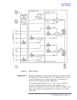
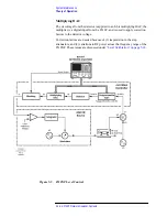
The correction factors are collected by means of a special calibration
procedure (detector gain calibration), in which the programmable gain
circuit is stepped through its range, at a fixed frequency. The process is then
repeated at a second frequency. (The two calibration frequencies are
specified in the firmware; they are chosen in order to achieve the greatest
possible leveling range.) Refer to
Frequency-related variations
The RF-to-IF conversion loss of a mixer varies with frequency. To
counteract these variations, a second set of correction factors is needed. This
set of correction factors is gathered by a special calibration procedure
(conversion loss calibration), in which the test ports are monitored with a
power meter while the 8510XF steps through its frequency range.
This calibration procedure is performed at the factory prior to shipment;
afterwards it is performed as required (to be performed by an Agilent
Technologies Customer Service engineer or the factory only). Refer to
Level control performance
Test port RF levels are controlled with a typical accuracy of
±
0.5 dB. The
level control range is at least 20 dB, if the entire frequency range of the
8510XF is used. If a smaller portion of the frequency range is used, the level
control range is typically greater.
LO Levels
The LO signal from the 83621B is amplified, divided, and distributed to the
various mixers in the test heads (and in the millimeter-wave controller, in the
case of the optional 0.045–2 GHz band). Each mixer must receive an LO
input signal that has been sufficiently amplified to satisfy its input level
requirements.
The mixers used for frequencies below 50 GHz are not highly sensitive to
variations in the level of the LO input signal, provided that the minimum
required input is present. However, the mixers used for frequencies above
50 GHz require LO input levels within a relatively narrow window. In order
to insure that the LO inputs to these mixers stay within acceptable limits, a
leveling loop is included in each test head.
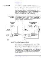
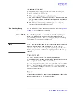
Each of the two LO leveling loops consists of an amplifier, coupler, pad,
detector, and ALC circuit, all located within the microwave subassembly of
the test head.
•
The LO input to the loop (received from the millimeter-wave controller)
is applied, though the amplifier and coupler, to the millimeter-wave
subassembly, where it is distributed to the >50 GHz mixers.
•
The coupled LO signal is applied, through a pad, to a diode detector.
Summary of Contents for 8510XF
Page 11: ...8510XF Network Analyzer Systems xi Compliance with Standards ...
Page 12: ...xii 8510XF Network Analyzer Systems Compliance with Standards ...
Page 136: ...4 18 8510XF Network Analyzer Systems Performance Verification CW Frequency Accuracy Test ...
Page 160: ...5 24 8510XF Network Analyzer Systems System Maintenance System Block Diagrams ...
Page 162: ...5 26 8510XF Network Analyzer Systems System Maintenance System Block Diagrams ...
Page 164: ...5 28 8510XF Network Analyzer Systems System Maintenance System Block Diagrams ...
Page 168: ...5 32 8510XF Network Analyzer Systems System Maintenance System Block Diagrams ...
Page 170: ...5 34 8510XF Network Analyzer Systems System Maintenance System Block Diagrams ...
Page 172: ...5 36 8510XF Network Analyzer Systems System Maintenance System Block Diagrams ...
Page 176: ...5 40 8510XF Network Analyzer Systems System Maintenance Troubleshooting ...
Page 188: ...6 12 8510XF Network Analyzer Systems Replaceable Parts Millimeter Wave Controller ...
Page 191: ...R ...
Page 192: ...R ...
Page 193: ...R ...
Page 194: ...R ...
Page 195: ...R ...
Page 196: ...R ...
Page 197: ...R ...
Page 198: ...HP E7350 calmckit cdr Rev 1 3 10 98 Menu Maps Cal Modify Cal Kit 7 17 7 18 ...
Page 199: ...R ...
Page 200: ...R ...
Page 201: ......
Page 202: ...R ...
Page 203: ...R ...
Page 204: ...R ...
Page 205: ...R ...
Page 206: ...R ...
Page 207: ...R ...
Page 208: ...R ...
Page 209: ...R ...
Page 210: ...R ...

