98
Installation and User’s Guide
3
Verifying System Functionality
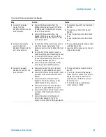
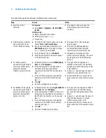
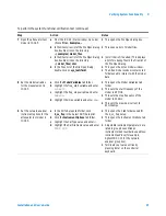
10 Configure the instrument
state for calibration.
a Disconnect the attenuator from the
semi-rigid cables.
b In the Utility key group on the network
analyzer front panel, press Macro/Local >
Preset.
c In the Channel menu, click Power... .
d In the Power dialog box, scroll the Test Port
Power value to
−
20 dBm
, then click OK.
e In the Sweep menu, point to Number of
Points and click 101.
f
In the Sweep menu, select IF Bandwidth... .
g In the IF Bandwidth dialog box, scroll to
1.000 kHz
, then click OK.
h In the Sweep menu, select Sweep Setup... .
i
In the Sweep Setup dialog box, select the
Stepped Sweep check box and click OK.
•
This removes the instrument from GPIB
control, activates the front panel
interface, and returns the instrument to
its factory preset condition.
•
Actions c through h prepare the
network analyzer for a full range 2-port
calibration using the same instrument
state settings used by the IC-CAP
functional verification test macro.
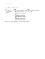
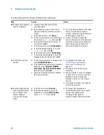
11 Calibrate the network
analyzer.
a In the network analyzer’s Calibration menu,
select Calibration Wizard... .
b In the Calibration Wizard: Begin Calibration
dialog box, select SmartCal (GUIDED
Calibration): Use Mechanical Standards
radio button and click Next.
c Follow the displayed prompts to calibrate
the network analyzer.
•
For detailed instructions, see
“Performing a Coaxial System
Measurement Calibration"
on
page 115.
•
This begins a modified full 2-port
calibration.
•
When prompted to connect a standard
to either Port 1 or Port 2, connect the
standard to the semi-rigid cable
attached to the Port 1 or Port 2 bias
network.
•
An isolation calibration is not needed
for this measurement.
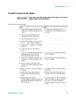
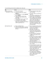
12 Save the calibration and
instrument state data to
the C:/Program Files/
Agilent /Network
Analyzer/Documents
folder.
a In the File menu, select Save As... .
b In the Save As dialog box, using the
keyboard or by clicking Edit File Name,
enter
TEST.CST
then click OK.
•
This saves the calibration and
instrument state data in the network
analyzer’s operating system
C:/Program Files/Agilent/
Network Analyzer/Documents folder.
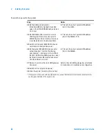
To perform the system functional verification test (continued)
Step
Action
Notes
Summary of Contents for 85225F
Page 1: ...Agilent Technologies Agilent 85225F PerformanceModelingSystem Installation and User s Guide ...
Page 90: ...90 Installation and User s Guide 2 Installing the System ...
Page 102: ...102 Installation and User s Guide 3 Verifying System Functionality ...
Page 110: ...110 Installation and User s Guide 4 Servicing the System ...
Page 118: ...118 Installation and User s Guide A Enhancing Measurement Accuracy ...
Page 128: ...128 Installation and User s Guide C RF Subsystem Functional Verification Test ...


