background image

Programming

Commands

(alphabetical

index)

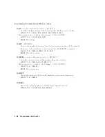
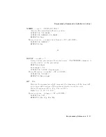
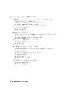
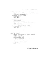
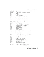
SR

CPSWP[

] <real >DBj

(UP j DN j ONj OFF j EP

j O

A) j ?;

Sw

eeps

the

output

p o

w

er

of

the

tracking

generator

o

v

er

the

c

hosen

p o

w

er-sw

eep

range.

<real >::=

0

to

12.75

UP/DN

incremen

t::=

0.1

dB

OUTPUT

;718;;"SCRPWR

-10DBM;SRCPSWP

10DB;TS;"

Query

resp onse:

<n

umeric

data

format ><

LF

with

EOI

>

OUTPUT

718;"SRCPSWP?;"

ENTER

718;Psweep

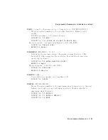
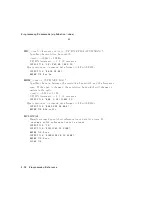
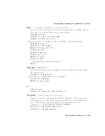
SR

CPWR[

] <real ><

amplitude

units >j

(ONj OFF j UPjDN j EP jO

A) j ?;

Activ

ates

the

output

p o

w

er

of

the

8560E/EC

Option

002

T

rac

king

Generator.

<real >::=

010

to

2.8

OUTPUT

718;"SRCPWR

ON;TS;DONE?;"

ENTER

718;Done

Query

resp onse:

(1 j 0) <LF

with

EOI

>

OUTPUT

718;"SRCPWR?;"

ENTER

718;Srcpower

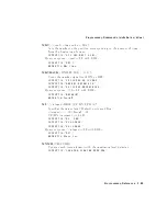
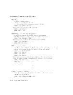
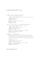
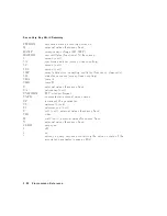
SR

CTKPK ;

Activ

ates

a

routine

that

adjusts

b oth

the

coarse-

and

ne-trac

king

adjustmen

ts

to

obtain

the

p eak

resp onse.

OUTPUT

718;"SRCPWR

ON;"

OUTPUT

718;"SWPCPL

SR;"

OUTPUT

718;"SRCTKPK;DONE?;"

ENTER

718;Done

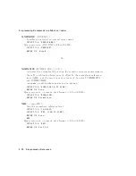
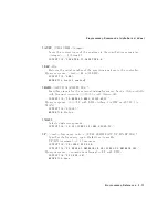
SR

Q[

] <in

teger >;

Sets

a

service

request

if

the

op erand

bits

are

allo

w

ed

b

y

R

QS.

<in

teger >::=

0

through

255

OUTPUT

718;"RQS

4;SRQ

4;"

5-80

Programming

Reference

Summary of Contents for 8560 E-Series

Page 1: ...0 E Series and EC Series Spectrum Analyzers Manufacturing Part Number 08560 90159 Printed in USA November 2000 Copyright 1993 2000 Agilent Technologies Silicon Investigations Repair Information Contact Us 920 955 3693 www siliconinvestigations com ...

Page 2: ... a particular purpose Agilent Technologies shall not be liable for errors contained herein or for incidental or consequential damages in connection with the furnishing performance or use of this material c Copyright Agilent Technologies 1993 2000 All Rights Reserved Reproduction adaptation or translation without prior written permission is prohibited except as allowed under the copyright laws 1400...

Page 3: ...measurement procedure Chapter 3 diagrams the front panel key location menus Chapter 4 documents front panel key and softkey functions Chapter 5 documents programming commands and information Chapter 6 documents the error messages Appendix A provides simpli ed block diagrams of the instruments For additional instrument information consult the Agilent Technologies 8560 E Series and EC Series Spectru...

Page 4: ......

Page 5: ...nel Key Functions Finding the Front Panel Key 4 2 Key Descriptions 4 15 5 Programming Reference Programming Commands functional index 5 2 Key versus Programming Command 5 22 Mass Memory Module Commands 5 37 Programming Commands alphabetical index 5 42 Notation Conventions 5 88 Syntax Conventions 5 89 Secondary Key Word Summary 5 90 6 Error Messages A Block Diagrams Contents 1 ...

Page 6: ......

Page 7: ...010 dBm Reference Level 2 5 2 5 Peaked Signal to Reference Level 2 7 Tables 1 1 Front Panel Connector Data 1 4 4 1 Front Panel Softkey Access 4 2 4 2 Conversion Loss Flatness Data 4 21 4 3 External Mixing Frequency Bands and Recommended Harmonics For Unpreselected External Mixers 4 25 5 1 Front Panel Key Versus Command 5 22 5 2 Mass Memory Module Commands 5 37 6 1 Remote Operation Errors 6 2 6 2 D...

Page 8: ......

Page 9: ...he front panel and rear panel keys and connectors on the 8560 E Series and EC Series spectrum analyzers Complete descriptions of each front panel function are in Chapter 5 of the 8560 E Series and 8560 EC Series User s Guide Instrument Overview 1 1 ...

Page 10: ...ATE functions generally a ect the state of the entire spectrum analyzer not just the state of a single function 3 MARKER functions read out frequencies and amplitudes along the spectrum analyzer trace let you make relative measurements automatically locate the signal of highest amplitude on a trace and tune the analyzer to track a signal automatically 4 CONTROL functions allow you to adjust the re...

Page 11: ...o the volume of the built in speaker The LINE button turns the spectrum analyzer on and o The LED above the LINE button indicates whether or not ac power is applied to the spectrum analyzer Caution Do not exceed the maximum safe input levels This can damage the input attenuator and the input mixer The maximum input level to the 50 RF input is 30 dBm with a minimum of 10 dB input attenuation The 85...

Page 12: ...dc coupled Option 006 30 Hz 26 5 GHz dc coupled 30 dBm Max 0 2 V dc Max dc coupled 8564E EC 9 kHz 40 GHz dc coupled Option 006 30 Hz 40 GHz dc coupled 30 dBm Max 0 2 V dc Max dc coupled 8565E EC 9 kHz 50 GHz dc coupled Option 006 30 Hz 50 GHz dc coupled 30 dBm Max 0 2 V dc Max dc coupled PROBE POWER 15 V 012 6 V 150 mA max CAL OUTPUT 300 MHz 010 dBm 60 3 dB IF INPUT for use with external mixers 31...

Page 13: ...This page intentionally left blank Instrument Overview 1 5 ...

Page 14: ...linear amplitude scale per division 3 Marker amplitude and frequency 4 Title area 5 Data invalid indicator displayed when analyzer settings are changed before completion of a full sweep 6 Menu title and softkey menu 7 Error message area 8 Frequency span or stop frequency 1 6 Instrument Overview ...

Page 15: ...uations in use refer to tracking generator menus F Frequency o set is less than or greater than 0 Hz G Internal tracking generator is ON K Signal track is ON M Trace math is ON N Normalization is ON R Reference level o set is less than or greater than 0 dB S Single sweep mode T Trigger mode set to line video or external W Amplitude correction ampcor is ON X 10 MHz reference is external External mi...

Page 16: ...and the 8560 EC series are shown in Figure 1 3 and Figure 1 4 8560 E series and EC series instruments are functionally identical except that 8560 EC series instruments o er a VGA port Descriptions of these functions follow Figure 1 3 8560 E Series Rear Panel 1 8 Instrument Overview ...

Page 17: ...nel Caution To prevent damage to the instrument be sure to set the voltage selector to the appropriate value for your local line voltage output Item 9 in Figure 1 3 For more information refer to the user s guide Instrument Overview 1 9 ...

Page 18: ... output The blanking output is 0 V to 5 V TTL that is low 0 V during spectrum analyzer sweeps The output is high 5 V during retrace and when the instrument is between bands in multiband sweeps Use the blanking output for pen lift when plotting with nondigital plotters This output is also useful for synchronizing instruments When used as the gate output it provides a TTL signal that indicates the s...

Page 19: ...12 J8 provides di erent selectable outputs a 0 V to 10 V ramp corresponding to the sweep ramp that tunes the local oscillator or a sweeping dc output of 0 5 V GHz 0 25 V GHz is also available with the 8564E EC and 8565E EC The output can be selected from the softkeys available when you press 4AUX CTRL5 and NNNNNNNNNNNNNNNNNNNNNNNNNNNNNNNN REAR PANEL External tracking generators such as the 85640A ...

Page 20: ......

Page 21: ...yzer to place a signal on the screen then measuring the frequency and amplitude of the signal with a marker We can measure an input signal in four simple steps 1 Set the center frequency 2 Set the frequency span 3 Activate the marker 4 Set the amplitude Making a Basic Measurement 2 1 ...

Page 22: ...ENCY5 This activates the center frequency function indicated by CENTER appearing in the active function block on the left side of the display See Figure 2 1 To set the center frequency to 300 MHz use the keys in the DATA section of the front panel to enter 300 MHz These data keys allow you to select the exact numeric value of the active function which in this case is the center frequency The step ...

Page 23: ...STEP 4 5 key to step down to this value Like data keys step keys can also be used to change the numeric value of the active function The resulting display is shown in Figure 2 2 Note that the resolution and video bandwidths are coupled to the frequency span they are automatically adjusted to appropriate values for a given span Sweep time is a coupled function also Figure 2 2 20 MHz Frequency Span ...

Page 24: ...ace in this case at or near the peak of the signal Use the knob to place the marker at the peak of the signal The marker reads both the frequency and the amplitude and displays these values in the active function block In this case the marker reads 300 00 MHz and 010 00 dBm as shown in Figure 2 3 Figure 2 3 Activated Normal Marker 2 4 Making a Basic Measurement ...

Page 25: ... LVL which is located under the 4MKR 5 key This function sets the reference level equal to the marker amplitude value See Figure 2 4 When no marker is active to adjust the signal peak to the reference level press 4AMPLITUDE5 then key in 010 dBm or use either the step keys or the knob Using the knob is the easiest way to ne tune the signal peak to the reference level which is located at the top of ...

Page 26: ...unction To calibrate the spectrum analyzer use the knob on the front panel to adjust the peak of the signal to the reference level as shown in Figure 2 5 Note the number that appears in the active function block In this example the number 0 appears when the signal is adjusted This number which ranges from 0528 to 528 033 to 33 for rmware revisions 920528 is a relative value indicating how much amp...

Page 27: ...librating the reference level is usually necessary only when the ambient temperature changes more than 10 C Because the spectrum analyzer continually monitors and reduces any IF errors executing the reference level calibration is seldom necessary Making a Basic Measurement 2 7 ...

Page 28: ......

Page 29: ...3 Menu Trees This chapter illustrates the di erent softkey menus available when pressing the front panel keys Menu Trees 3 1 ...

Page 30: ...NNNNNNNNNNNNNNNNNNNNNNN NORMLIZE ON OFF is set to ON y Available only with internal mixing z Not available for an 8563E EC 8564E EC or 8565E EC x Available only when NNNNNNNNNNNNNNNNNNNNNNNNNNNNNNNNNNNNNNNNNNN NORMLIZE ON OFF is set to ON k Not available for an 8560E EC 3 2 Menu Trees ...

Page 31: ... Available only with internal mixing Menu Trees 3 3 ...

Page 32: ...3 4 Menu Trees ...

Page 33: ...NNNNNNNNNNNNNNNNNNNNNNNNN INTERNAL MIXER are not available NNNNNNNNNNNNNNNNNNNNNNNNNNNNNNNNNNNNNNNN EXTERNAL MIXER is not shown for an 8560E with Option 002 installed and it is non functional for Option 327 y Signal identi cation functions are only available in non preselected external mixing mode with rmware revisions 920528 or with Option 008 installed z This key changes to NNNNNNNNNNNNNNNNNNNNN...

Page 34: ...3 6 Menu Trees ...

Page 35: ...ed z This key is displayed only if unpreselected external mixing is selected NNNNNNNNNNNNNNNNNNNNNNNNNNNNNNNNNNNNNNNNNNNNNN EXT MXR PRE UNPR is set to NNNNNNNNNNNNN UNPR x This key is displayed only if preselected external mixing is selected NNNNNNNNNNNNNNNNNNNNNNNNNNNNNNNNNNNNNNNNNNNNNN EXT MXR PRE UNPR is set to NNNNNNNNNN PRE k This key changes to NNNNNNNNNNNNNNNNNNNNNNNNNNNNNNNNNNN MARKER DELT...

Page 36: ...3 8 Menu Trees ...

Page 37: ...ADJ is pressed y Changes to NNNNNNNNNNNNNNNNNNNNNNNNNNNNNNNNNNNNN STORE REF LVL if NNNNNNNNNNNNNNNNNNNNNNNNNNNNNNNN REF LVL ADJ is pressed z These functions are only available with rmware revisions 930809 x The CRT adjust pattern is used to help align the display of E series instruments Menu Trees 3 9 ...

Page 38: ...ption 002 or Option 327 z Both E series and EC series instruments appear as E series in the instrument display when the DATECODE OPTION key is pressed EC series instruments also appear as Option 007 instruments Option 007 is the FADC option which is standard in all EC series instruments 3 10 Menu Trees ...

Page 39: ...ruments do not require adjustment therefore the intensity adjustment is not active for 8560 EC Series instruments y Changes to NNNNNNNNNNNNNNNNNNNNNNNNNNNNNNNN STORE FOCUS if NNNNNNNNNNNNNNNN FOCUS is pressed Note 8560 EC Series instruments do not require adjustment therefore the focus is not active for EC Series instruments Menu Trees 3 11 ...

Page 40: ...3 12 Menu Trees ...

Page 41: ... NNNNNNNNNNNNNNNNNNNNNNNNNNNNNNNN MORE 1 OF 2 is displayed under 4FREQUENCY5 only on spectrum analyzers with rmware revision 960401 and later Menu Trees 3 13 ...

Page 42: ...3 14 Menu Trees ...

Page 43: ...wer power and adjacent channel power ACP functions y See the following gure for ACP setup menus z The NNNNNNNNNNNNN SPAN softkey is displayed if the markers are not active x Present only when this menu is accessed from the occupied power menu Menu Trees 3 15 ...

Page 44: ... The NNNNNNNNNNNNNNNNNNNNNNNN ACP MENU softkey is under the 4MEAS USER5 key See the preceding gure y Available with rmware 930809 z Available with rmware 931216 3 16 Menu Trees ...

Page 45: ...Menu Trees 3 17 ...

Page 46: ...tkeys y 4MODULE5 accesses these additional softkeys if the 85629B test and adjustment module TAM is attached to the spectrum analyzer See the 85629B documentation for more information about these softkeys The 85629B is not compatible with the 8564E EC or 8565E EC Note The 8562E TAM Interface Software is required when using the TAM with the 8562E spectrum analyzer 3 18 Menu Trees ...

Page 47: ... Changes to NNNNNNNNNNNNNNNNNNNNNNNNNNNNNNNNNNNNN MARKER NORMAL if the spectrum analyzer is in zero span or NNNNNNNNNNNNNNNNNNNNNNNNNNNNNNNNNNN MARKER DELTA is active Menu Trees 3 19 ...

Page 48: ... Available only with internal mixing above 2 9 GHz y Available with preselected external mixing Available with internal mixing above 2 9 GHz 3 20 Menu Trees ...

Page 49: ... Available with preselected external mixing Available with internal mixing above 2 9 GHz Menu Trees 3 21 ...

Page 50: ...NNNNNNNNNNNNNNNNNNNNNNNNN GATE CTL EDGE LVL is set to level LVL y This softkey becomes NNNNNNNNNNNNNNNNNNNNNNNNNNNNNNNNNNNNNNNNNNN LVL POL POS NEG if NNNNNNNNNNNNNNNNNNNNNNNNNNNNNNNNNNNNNNNNNNNNNNNN GATE CTL EDGE LVL is set to level LVL 3 22 Menu Trees ...

Page 51: ...Menu Trees 3 23 ...

Page 52: ......

Page 53: ...nd each softkey If you know the front panel key you can use the menu trees to locate the key After the table every front panel key and softkey is listed Next to each key label is a brief description of its operation For more detailed descriptions of the keys refer to the Agilent Technologies 8560 E Series and EC Series Spectrum Analyzers User s Guide Front Panel Key Functions 4 1 ...

Page 54: ... 6dB POINTS 4MEAS USER5 NNNNNNNNNNNNNNNNNN A B A 4TRACE5 NNNNNNNNNNNNNNNNNNNNNNNNNNNNNNNNNNNNN A B A ON OFF 4TRACE5 NNNNNNNNNNNNNNNNNNNNNNNNNNNNNNNNNNNNNNNNNNNNN A B DL A ON OFF 4TRACE5 NNNNNNNNNNNNNNNNNNNNNNNN A EXCH B 4TRACE5 NNNNNNNNNNNNNNNNNNNNNNNN ACCELRAT 4MEAS USER5 NNNNNNNNNNNNNNNNNNNNNNNNNNNNNNNNNNNNNNNNNNN ACCELRAT FASTER 4MEAS USER5 NNNNNNNNNNNNNNNNNNNNNNNNNNNNNNNNNNNNNNNNNNNNNN ACCELRA...

Page 55: ...NN ANALOG METHOD 4MEAS USER5 NNNNNNNNNNNNNNNNNNNNNNNNNNNNN ANNOT HELP 4DISPLAY5 NNNNNNNNNNNNNNNNNNNNNNNNNNNNNNNNNNN ANNOT ON OFF 4DISPLAY5 NNNNNNNNNNNNNNNNNNNNNNNNNNNNNNNNNNNNNNNNNNN AM DEMOD ON OFF 4AUX CTRL5 NNNNNNNNNNNNNNNNNNNNNNNNNNNNNNNN AM FM DEMOD 4AUX CTRL5 NNNNNNNNNNNNNNNNNNNNNNNNNNNNNNNNNNNNN AMPTD CORRECT 4AUX CTRL5 NNNNNNNNNNNNNNNNNNNNNNNNNNNNNNNN AMPTD UNITS 4AMPLITUDE5 NNNNNNNNNNNNNN...

Page 56: ...NNNNNNNNNNN BURST PERIOD 4MEAS USER5 NNNNNNNNNNNNNNNNNNNNNNNNNNNNNNNNNNNNNNNNNNN BURSTPWR METHOD 4MEAS USER5 NNNNNNNNNNNNNNNNNNNNNNNNNNNNNNNNNNN CAL OPN SHRT 4AUX CTRL5 NNNNNNNNNNNNNNNNNNNNNNNN CAL THRU 4AUX CTRL5 NNNNNNNNNNNNNNNNNNNNNNNNNNNNNNNNNNNNNNNNNNNNNN CARRIER PWR MENU 4MEAS USER5 NNNNNNNNNNNNNNNNNNNNNNNNNNNNNNNN CENTER FREQ 4FREQUENCY5 NNNNNNNNNNNNNNNNNNNNNNN CF 2 CF 4FREQUENCY5 NNNNNNNNN...

Page 57: ... 1 2 4DISPLAY5 NNNNNNNNNNNNNNNNNNNNNNNNNNNNNNNNNNNNNNNNNNN CHPWR BW 4MEAS USER5 NNNNNNNNNNNNNNNNNNNNNNNNNNNNNNNNNNNNN CLEAR WRITE A 4TRACE5 NNNNNNNNNNNNNNNNNNNNNNNNNNNNNNNNNNNNN CLEAR WRITE B 4TRACE5 NNNNNNNNNNNNNNNNNNNNNNNNNNNNNNNNNNNNNNNNNNNNNN CNV LOSS VS FREQ 4AUX CTRL5 NNNNNNNNNNNNNNNN COLOR 4CONFIG5 NNNNNNNNNNNNNNNNNNNNNNNNNNNNNNNNNNN CONT MEASURE 4MEAS USER5 NNNNNNNNNNNNNNNNNNNNNNNNNNNNNNNN...

Page 58: ... NORMAL 4TRACE5 NNNNNNNNNNNNNNNNNNNNNNNNNNNNNNNNNNNNNNNNNNNNNNNN DETECTOR POS PEAK 4TRACE5 NNNNNNNNNNNNNNNNNNNNNNNNNNNNNNNNNNNNNNNNNNN DETECTOR SAMPLE 4TRACE5 NNNNNNNNNNNNNNNNNNNNNNNNNNNNNNNNNNNNNNNN DLY SWP 4SWEEP5 NNNNNNNNNNNNNNNNNNNNNNNNNNNNNNNNNNNNNNNN DLY SWP ON OFF 4SWEEP5 NNNNNNNNNNNNNNNNNNNNNNNNNN DONE EDIT 4CAL5 NNNNNNNNNNNNNNNNNNNNNNNNNNNNNNNNNNNNNNNNNNN DSPL LIN ON OFF 4DISPLAY5 NNNNNNN...

Page 59: ...NNNNNNNNNNNNNNNNN FM DEMOD ON OFF 4AUX CTRL5 NNNNNNNNNNNNNNNN FOCUS 4DISPLAY5 NNNNNNNNNNNNNNNNNNNNNNNNNNNNNNNN FRAC N FREQ 4CAL5 NNNNNNNNNNNNNNNNNNNNNNNN FREE RUN 4TRIG5 NNNNNNNNNNNNNNNNNNNNNNNNNNNNNNNNNNNNN FREQ DIAGNOSE 4CAL5 NNNNNNNNNNNNNNNNNNNNNNNNNNNNNNNNNNN FREQ DSP OFF 4DISPLAY5 NNNNNNNNNNNNNNNNNNNNNNNNNNNNNNNN FREQ OFFSET 4FREQUENCY5 NNNNNNNNNNNNNNNNNNNNNNNNNN FULL BAND 4AUX CTRL5 NNNNNNNN...

Page 60: ...NNNNNNNNNNNN LAST STATE 4PRESET5 4RECALL5 NNNNNNNNNNNNN LINE 4TRIG5 NNNNNNNNNNNNNNNNNN LINEAR 4AMPLITUDE5 NNNNNNNNNNNNNNNNNNNNN LO FREQ 4CAL5 NNNNNNNNNNNNNNNNNNNNNNNNNNNNNNNNNNNNN LOCK HARMONIC 4AUX CTRL5 NNNNNNNNNNNNNNNNNNNNNNNNNNNNNNNN LOCK ON OFF 4AUX CTRL5 NNNNNNNNNNNNNNNNNNNNNNNNNNNNN LOG dB DIV 4AMPLITUDE5 NNNNNNNNNNNNNNNNNNNNNNNNNNNNNNNNNNNNNNNNNNN LVL POL POS NEG 4SWEEP5 NNNNNNNNNNNNNNNNNN...

Page 61: ...LEVEL 4AMPLITUDE5 NNNNNNNNNNNNNNNNNNNNN METHODS 4MEAS USER5 NNNNNNNNNNNNNNNNNNNNNNNNNNNNNNNN MKR 1 CF 4MKR 5 NNNNNNNNNNNNNNNNNNNNNNNNNNNNNNNNNNNNNNNNNNNNN MKR 1 CF STEP 4MKR 5 NNNNNNNNNNNNNNNNNNNNNNNNNNNNNNNNNNNNNNNNNNNNNNNN MKR 1 CHPWR BW 4MEAS USER5 NNNNNNNNNNNNNNNNNNNNNNNNNNNNNNNNNNNNN MKR 1 SPAN 4MKR 5 NNNNNNNNNNNNNNNNNNNNNNNNNNNNNNNNNNNNN MKR 1 1 CF 4MKR 5 NNNNNNNNNNNNNNNNNNNNNNNNNNNNNNNNNNNN...

Page 62: ...NNNNNNNNNNNNNNNNNN OCCUPIED PWR MENU 4MEAS USER5 NNNNNNNNNNNNNNNNNNNNNNNNNNNNNNNNNNN PEAK EXCURSN 4PEAK SEARCH5 NNNNNNNNNNNNNNNNNNNNNNNNNNNNNNNN PEAK METHOD 4MEAS USER5 NNNNNNNNNNNNNNNNNNNNNNNNNNNNNNNN PEAK SEARCH 4AUX CTRL5 4FREQ COUNT5 4CAL5 NNNNNNNNNNNNNNNNNNNNNNNNNNNNNNNNNNNNN PEAK THRESHLD 4PEAK SEARCH5 NNNNNNNNNNNNNNNNNNNNNNNNNNNNN PLOT ANNOT 4CONFIG5 NNNNNNNNNNNNNNNNNNNNNNNNNNNNNNNNNNNNN PL...

Page 63: ...NNNNNNNNNNNNNNNNNNNNNNNNNNNNNNNNNN PWR ON STATE 4SAVE5 NNNNNNNNNNNNNNNNNNNNNNNNNNNNNNNNNNNNN PWR MENU HELP 4MEAS USER5 NNNNNNNNNNNNNNNNNNNNNNNNNNNNNNNNNNNNNNNN PWR SWP ON OFF 4AUX CTRL5 NNNNNNNNNNNNNNNNNNNNNNNNNN RANGE LVL 4AMPLITUDE5 4AUX CTRL5 NNNNNNNNNNNNNNNNNNNNNNNNNNNNNNNNNNN RAW OSC FREQ 4CAL5 NNNNNNNNNNNNNNNNNNNNNNNNNNNNNNNNNNNNNNNN RBW SPAN RATIO 4BW5 NNNNNNNNNNNNNNNNNNNNNNNNNNNNNNNNNNNNNN...

Page 64: ...NNNNNNNN RES BW AUTO MAN 4AUTO COUPLE5 4BW5 NNNNNNNNNNNNNNNNNNNNNNNNNNNNNNNNNNN SAMPLER FREQ 4CAL5 NNNNNNNNNNNNNNNNNNNNNNNNNNNNNNNNNNNNNNNNNNNNNN SAMPLER HARMONIC 4CAL5 NNNNNNNNNNNNNNNNNNNNNNNNNNNNNNNN SAVE AMPCOR 4CAL5 NNNNNNNNNNNNNNNNNNNNNNNNNNNNNNNNNNNNN SAVE PRSEL PK 4SAVE5 NNNNNNNNNNNNNNNNNNNNNNNNNNNNN SAVE STATE 4SAVE5 NNNNNNNNNNNNNNNNNNNNNNNNNNNNNNNNNNN SAVE TRACE A 4SAVE5 NNNNNNNNNNNNNNNNN...

Page 65: ...NNNNNNNNNNNNNNNNNNNNNNNNNNNNNNNNNNN SPACING BANDWDTH 4MEAS USER5 NNNNNNNNNNNNN SPAN 4SPAN5 NNNNNNNNNNNNNNNNNNNNNNNNNN SPAN ZOOM 4SPAN5 NNNNNNNNNNNNNNNNNNNNNNNNNNNNNNNNNNNNNNNN SQUELCH ON OFF 4AUX CTRL5 NNNNNNNNNNNNNNNNNNNNNNNNNNNNNNNNNNNNNNNN SRC PWR OFFSET 4AUX CTRL5 NNNNNNNNNNNNNNNNNNNNNNNNNNNNNNNNNNNNNNNN SRC PWR ON OFF 4AUX CTRL5 NNNNNNNNNNNNNNNNNNNNNNNNNNNNNNNNNNNNNNNNNNNNNN SRC PWR STP SIZE ...

Page 66: ...TO MAN 4AMPLITUDE5 4AUTO COUPLE5 NNNNNNNNNNNNNNNNNNNNNNNNNNNNNNNNNNNNN VBW RBW RATIO 4BW5 NNNNNNNNNNNNNNNNNNNNNNNNNNNNNNNNNNNNN V GHz 25 50 4AUX CTRL5 NNNNNNNNNNNNNNNNNN VIEW A 4TRACE5 NNNNNNNNNNNNNNNNNN VIEW B 4TRACE5 NNNNNNNNNNNNNNNNNNNNNNNNNNNNNNNNNNNNN VIEW TBL TRCE 4MEAS USER5 NNNNNNNNNNNNNNNNNNNNNNNNNNNNNNNNNNNNNNNN VID AVG ON OFF 4BW5 4TRACE5 NNNNNNNNNNNNNNNN VIDEO 4TRIG5 NNNNNNNNNNNNNNNNNN...

Page 67: ...erators NNNNNNNNNNNNNNNNNNNNNNNNNNNNNNNN 2BW METHOD Makes an ACP measurement using two di erent resolution bandwidths NNNNNNNNNNNNNNNNNNNNNNNNNNNNNNNN 3dB POINTS A peak search is performed and the 3 dB bandwidth of the largest signal on screen is displayed in the active function area NNNNNNNNNNNNNNNNNNNNNNNNNNNNNNNN 6dB POINTS A peak search is performed and the 6 dB bandwidth of the largest signal...

Page 68: ...peci ed by the standards NNNNNNNNNNNNNNNNNNNNNNNNNNNNNNNNNNNNNNNNNNNNNNNNNN ACP AUTO MEASURE Measures the power that leaks from the transmitter output into the channels that are adjacent to the carrier NNNNNNNNNNNNNNNNNNNNNNNNNNNNNNNNNNN ACP COMPUTE Performs an adjacent channel power ACP computation on the current trace data without changing the instrument state settings NNNNNNNNNNNNNNNNNNNNNNNNNN...

Page 69: ...ts NNNNNNNNNNNNNNNNNNNNNNNNNNNNNNNNNNNNNNNNNNNNNNN AM DEMOD ON OFF Turns AM demodulation on and o NNNNNNNNNNNNNNNNNNNNNNNNNNNNNNNNNNN AM FM DEMOD Accesses functions for AM or FM demodulation NNNNNNNNNNNNNNNNNNNNNNNNNNNNNNNNNNN AMPCOR MENU Accesses functions that allow you to enter amplitude correction ampcor factors to correct system atness NNNNNNNNNNNNNNNNNNNNNNNNNNNNNNNNNNNNNNNNN AMPCOR ON OFF T...

Page 70: ...rnal mixer external mixer demodulation and rear panel functions NNNNNNNNNNNNNNNNNNNNNNNNNNNNNNNNNNNNNNNNNNNNNNNNNN AVERAGE CNV LOSS Displays the mean conversion loss for the current harmonic and allows you to enter new conversion loss data Any change to the average conversion loss also a ects atness data Not available with an 8560E EC Option 002 and non functional in Option 327 NNNNNNNNNNNNNNNNNNN...

Page 71: ...bandwidth related functions 4CAL5 Accesses the menu of calibration functions NNNNNNNNNNNNNNNNNNNNNNNNNNNNNNNNNNNNNN CAL OPN SHRT Measures and computes the average of an open and a short input calibration then stores the data in trace B and in instrument state register 8 Use when making re ection measurements with a tracking generator NNNNNNNNNNNNNNNNNNNNNNNNNN CAL THRU Stores thru calibration in t...

Page 72: ...nt NNNNNNNNNNNNNNNNNNNNNNNNNNNNNNNNNNNNNNNNNNNNNNNNNN CHANNEL PWR MENU Accesses the channel power measurement functions NNNNNNNNNNNNNNNNNNNNNNNNNNNNNNNNNNNNNNNNNNNNNNN CHANNEL SPACING Sets the spacing between channels for an adjacent channel power ACP measurement NNNNNNNNNNNNNNNNNNNNNNNNNNNNNNNNNNNNNN CHAR SET 1 2 Accesses character sets used for creating titles NNNNNNNNNNNNNNNNNNNNNNNNNNNNNNNNNNN...

Page 73: ...s a menu of functions used to con gure a plotter and a printer as hard copy devices sets the spectrum analyzer GPIB address and views the instrument datecode and options NNNNNNNNNNNNNNNNNNNNNNNNNNNNNNNNNNNNNN CONT MEASURE Sets the measurements so that they run continuously 4COPY5 Copies the display contents onto a plotter or a printer NNNNNNNNNNNNNNNNNNNNNNNNNNNNNNNNNNNNNNNNNNNNNNNNNNNNN COPY DEV ...

Page 74: ...this key is pressed EC series instruments also appear as Option 007 instruments Option 007 is the FADC option which is standard in all EC series instruments NNNNNNNNNNNNNN dB V Selects absolute decibels relative to 1 microvolt as the amplitude units NNNNNNNNNNN dBm Selects absolute decibels relative to 1 milliwatt as the amplitude units NNNNNNNNNNNNNN dBmV Selects absolute decibels relative to 1 m...

Page 75: ...NNNNNNNNNNNNNNNNNNNN DSPL LIN ON OFF Switches the display line on and o NNNNNNNNNNNNNNNNNNNNNNNNNNNNNNNNNNNNNNNNNNNNNNNNNN EDGE POL POS NEG Selects the polarity for edge triggering of a gated measurement NNNNNNNNNNNNNNNNNNNNNNNNNNNNNNNNNNN EDIT AMPCOR Allows you to edit the ampcor correction points NNNNNNNNNNNNNNNNNNNNNNNNNNNNN EDIT AMPL Allows you to edit the amplitude of an ampcor correction poi...

Page 76: ...cy domain NNNNNNNNNNNNNNNNNNNNNNNNNNNNNNNNNNNNNNNNNNNNNNN FM DEMOD ON OFF Switches FM demodulation ON and OFF NNNNNNNNNNNNNNNNN FOCUS Permits focusing of the display for 8560 E Series instruments using the data keys the step keys or the knob Note 8560 EC Series instruments use a at panel display which does not require adjustment and is not adjustable NNNNNNNNNNNNNNNNNNNNNNNNNNNNNNNNNNN FRAC N FREQ...

Page 77: ...Frequency Bands and Recommended Harmonics For Unpreselected External Mixers Band Frequency Range Mixing Harmonic Conversion Loss K 18 6 26 5 GHz 60 30 dB A 26 5 40 0 GHz 80 30 dB Q 33 0 50 0 GHz 100 30 dB U 40 0 60 0 GHz 100 30 dB V 50 0 75 0 GHz 140 30 dB E 60 0 90 0 GHz 160 30 dB W 75 5 110 0 GHz 180 30 dB F 90 0 140 0 GHz 240 30 dB D 110 0 170 0 GHz 300 30 dB G 140 0 220 0 GHz 360 30 dB Y 170 0...

Page 78: ...the active function to its present value blanks the softkeys and active function area from the display and expands the remaining graticule and annotation NNNNNNNNNNNNNNNNNNNNNNNNNNNNNNNNNNNNNNNNN IF ADJ ON OFF Switches the automatic IF adjustment on and OFF When it is on various IF parameters are adjusted during retrace to ensure amplitude accuracy within speci cations NNNNNNNNNNNNNNNNNNNNNNNNNN I...

Page 79: ... non functional in Option 327 NNNNNNNNNNNNNNNNNNNNNNN LO FREQ Displays the rst local oscillator frequency corresponding to the current start frequency NNNNNNNNNNNNNNNNNNNNNNNNNNNNNNNN LOG dB DIV Selects a 1 2 5 or 10 dB per division logarithmic amplitude scale NNNNNNNNNNNNNNNNNNNNNNNNNNNNNNNNNNNNNNNNNNNNNNN LVL POL POS NEG Selects the polarity for turning the gate on when using level triggering fo...

Page 80: ...B NNNNNNNNNNNNNNNNNNNNNNNNNNNNNNNNNNNNNNNNN MAX MXR LEVEL Selects the maximum mixer level seen at the input mixer for signals at or below the reference level Internal mixing only 4MEAS USER5 Accesses softkeys that perform occupied power bandwidth adjacent channel power ACP and FFT measurements NNNNNNNNNNNNNNNNNNNNNNN METHODS Selects the measurement method that will be used to make the adjacent cha...

Page 81: ...present NNNNNNNNNNNNNNNNNNNNNNNNNNNNNNNNNNNNNNNNN NEGATIVE BIAS Selects negative bias for an external mixer Not available with a 8560E Option 002 and non functional in Option 327 NNNNNNNNNNNNNNNNNNNNNNNNNNNNNNNNNNN NEW CORR PT Allows you to create a new ampcor correction point NNNNNNNNNNNNNNNNNNNNNNNNNNNNN NEXT PEAK Moves the active marker to the next highest trace peak relative to the current mar...

Page 82: ...rker at the highest point on a trace and accesses a menu of marker functions NNNNNNNNNNNNNNNNNNNNNNNNNNNNNNNNNNN PEAK SEARCH Places a marker on the highest point on a trace and displays the marker frequency and amplitude NNNNNNNNNNNNNNNNNNNNNNNNNNNNNNNNNNNNNNNNN PEAK THRESHLD Sets the minimum amplitude level from which a peak on a trace can be detected NNNNNNNNNNNNNNNNNNNNNNNNNNNNNNNN PLOT ANNOT P...

Page 83: ...nel power and carrier power NNNNNNNNNNNNNNNNNNNNNNNNNN POWER ON Sets the instrument state to the state stored in the power on register NNNNNNNNNNNNNNNNNNNNNNNNNNNNNNNNNNNNNNNNNNNN PRESEL AUTO PK Automatically peaks the preselector for the selected signal on a trace NNNNNNNNNNNNNNNNNNNNNNNNNNNNNNNNNNNNNNNNNNNN PRESEL MAN ADJ Permits manual adjustment of the preselector Peak the preselector using th...

Page 84: ...NNNNNNNNNNNNNNNNNNNNNNNNNNNNNNNNNNNNNNNNN RBW SPAN RATIO Displays the current coupling ratio between the resolution bandwidth and the frequency span NNNNNNNNNNNNNNNNNNNNNNNNNNNNNNNNNNNNNNNNNNNNNNN REALIGN LO IF Activates the LO and IF alignment routines for a complete LO and IF alignment NNNNNNNNNNNNNNNNNNNNNNNNNNNNNNNN REAR PANEL Accesses a menu for selecting the signals available at the rear pan...

Page 85: ... calibration data into trace B and sets the instrument to the calibration state NNNNNNNNNNNNNNNNNNNNNNNNNNNNNNNNNNNNNNNNNNNN RECALL TO TR A Displays a menu of eight registers from which data can be recalled and placed in trace A NNNNNNNNNNNNNNNNNNNNNNNNNNNNNNNNNNNNNNNNNNNN RECALL TO TR B Displays a menu of eight registers from which data can be recalled and placed in trace B NNNNNNNNNNNNNNNNNNNNNN...

Page 86: ...plays the sampler harmonic number corresponding to the current start frequency 4SAVE5 Accesses a menu for storing instrument data NNNNNNNNNNNNNNNNNNNNNNNNNNNNNNNNNNN SAVE AMPCOR Saves the current table of amplitude correction ampcor points NNNNNNNNNNNNNNNNNNNNNNNNNNNNNNNNNNNNNNNNN SAVE PRSEL PK Saves the current preselector peak data in a data table For use with preselected external mixing or with...

Page 87: ...N SIG ID AT MKR Only available with rmware revisions 920528 or with Option 008 NNNNNNNNNNNNNNNNNNNNNNNNNNNNNNNNNNNNNNNNN SID ID ON OFF Switches manual signal identi cation on and o Signals that are correct for the selected band are identi ed by being shifted less than 50 kHz Limit frequency spans to less than 20 MHz for best performance Only available with rmware revisions 920528 or with Option 00...

Page 88: ...ckly without losing the signal from the display If no marker is present the peak search function is executed before the span is reduced See also NNNNNNNNNNNNNNNNNNNNNNNNNNNNNNNNNNNNNNNNNNNN SIG TRK ON OFF NNNNNNNNNNNNNNNNNNNNNNNNNNNNNNNNNNNNNNNNNNNN SQUELCH ON OFF Turns squelch on and o and adjusts the squelch level for demodulation NNNNNNNNNNNNNNNNNNNNNNNNNNNNNNNNNNNNNNNNNNNN SRC PWR OFFSET O set...

Page 89: ...iting of the current title 4TRACE5 Accesses a menu of trace functions NNNNNNNNNNNNNNNNNNNNNNNNNNNNN TRACE A B Accesses trace related functions for traces A and B NNNNNNNNNNNNNNNNNNNNNNNNNNNNNNNNNNNNNNNNNNNNNNNNNNNNN TRACKING GENRATOR Accesses a menu of tracking generator functions NNNNNNNNNNNNNNNNNNNNNNNNNNNNNNNNNNNNNNNNN TRACKING PEAK Adjusts the coarse and ne tracking adjustments to peak the tra...

Page 90: ...current contents of trace B but does not update the contents NNNNNNNNNNNNNNNNNNNNNNNNNNNNNNNNNNNNNNNNN VIEW TBL TRCE Sets the display to show a table of the ACP measurement results or to show a trace NNNNNNNNNNNNNNNNN VOLTS Selects volts as the display amplitude units NNNNNNNNNNNNNNNNN WATTS Selects watts as the display amplitude units NNNNNNNNNNNNNNNNNNNNNNNNNNN WEIGHT Enters the factor for root ...

Page 91: ...BASIC If you have a series of front panel key presses that you would like to write a program for there is a cross reference to help you nd the equivalent programming commands A list of the 85620A mass memory module commands can be found in the section on Module Commands Topics documented in this chapter include Programming Commands functional index Key versus Programming Command Mass Memory Module...

Page 92: ...re listed by function in this section The equivalent key or softkey and a brief description are also listed Alternate commands common to the 8560 E Series and the 8566A 8568A are included The alternate commands are shown in parentheses 5 2 Programming Reference ...

Page 93: ...NNNNNNNNNNNNNNNNN LOG dB DIV Speci es log scale LN NNNNNNNNNNNNNNNNNN LINEAR Speci es linear scale MKRL NNNNNNNNNNNNNNNNNNNNNNNNNNNNNNNNNNNNNNNNNNNNNNNN MARKER REF LVL Moves active marker amplitude to reference level E4 ML NNNNNNNNNNNNNNNNNNNNNNNNNNNNNNNN MAX MXR LVL Speci es the mixer level NRPOS NNNNNNNNNNNNNNNNNNNNNNNNNNNNNNNNNNNNN NORM REF POSN Adjusts the normalized reference position PP NNNN...

Page 94: ...UTO NNNNNNNNNNNNNNNNNNNNNNNNNNNNNNNNNNNNNNNNNNNNNNNN VIDEO BW AUTO MAN AUTO Auto couples video bandwidth CV VBR NNNNNNNNNNNNNNNNNNNNNNNNNNNNNNNNNNNNN VBW RBW RATIO Speci es coupling ratio of video bandwidth and resolution bandwidth AUXILIARY CONTROL CNVLOSS NNNNNNNNNNNNNNNNNNNNNNNNNNNNNNNNNNNNNNNNNNNNNN AVERAGE CNV LOSS Sets reference level o set to compensate for external mixer conversion loss DE...

Page 95: ...NNNNNNNNNNNNNNNNNNNNNNNNNNNNNNNN PEAK EXCURSN Speci es minimum excursion for peak identi cation MXRMODE NNNNNNNNNNNNNNNNNNNNNNNNNNNNNNNNNNNNNNNN EXTERNAL MIXER or NNNNNNNNNNNNNNNNNNNNNNNNNNNNNNNNNNNNNNNN INTERNAL MIXER Speci es either internal or external mixing NORMLIZE NNNNNNNNNNNNNNNNNNNNNNNNNNNNNNNNNNNNNNNNNNN NORMLIZE ON OFF Activates normalization routine NRL NNNNNNNNNNNNNNNNNNNNNNNNNNNNNNNN...

Page 96: ...erator source power SRCPSTP NNNNNNNNNNNNNNNNNNNNNNNNNNNNNNNNNNNNNNNNNNNNNN SRC PWR STP SIZE Sets the step size of the source power level SRCPSWP NNNNNNNNNNNNNNNNNNNNNNNNNNNNNNNNNNNNNNNN PWR SWP ON OFF Controls the power sweep function SRCPWR NNNNNNNNNNNNNNNNNNNNNNNNNNNNNNNNNNNNNNNN SRC PWR ON OFF Controls the output power of the tracking generator SRCTKPK NNNNNNNNNNNNNNNNNNNNNNNNNNNNNNNNNNNNN TRAC...

Page 97: ...eci es the coupling ratio of resolution bandwidth and frequency span VAVG NNNNNNNNNNNNNNNNNNNNNNNNNNNNNNNNNNNNNNNN VID AVG ON OFF Turns video averaging on or o VB NNNNNNNNNNNNNNNNNNNNNNNNNNNNNNNNNNNNNNNNNNNNNNNN VIDEO BW AUTO MAN Speci es video bandwidth VBR NNNNNNNNNNNNNNNNNNNNNNNNNNNNNNNNNNNNN VID RBW RATIO Speci es coupling ratio of video bandwidth and resolution bandwidth Programming Reference...

Page 98: ...A NNNNNNNNNNNNNNNNNNNNNNNNNNNNNNNN EDIT AMPCOR Enters amplitude correction data AMPCORSIZE Indicates the number of correction points AMPCORRCL NNNNNNNNNNNNNNNNNNNNNNNNNNNNNNNNNNNNN RECALL AMPCOR Recalls ampcor data AMPCORSAVE NNNNNNNNNNNNNNNNNNNNNNNNNNNNNNNN SAVE AMPCOR Saves ampcor data FDIAG NNNNNNNNNNNNNNNNNNNNNNNNNNNNNNNNNNNNN FREQ DIAGNOSE NNNNNNNNNNNNNNNNNNNNN LO FREQ NNNNNNNNNNNNNNNNNNNNNNN...

Page 99: ...NNNNNNNNNNNNNNNNNNNNNNNNNNNNNNNNN PLOT GRATICUL NNNNNNNNNNNNNNNNNNNNNNNNNNNNNNNNNNNNNNNNNNNNNNNN PLOT ORG DSP GRAT NNNNNNNNNNNNNNNNNNNNNNNNNNNNNNNNNNN PLOT TRACE A NNNNNNNNNNNNNNNNNNNNNNNNNNNNNNNNNNN PLOT TRACE B Speci es plot source PRINT 4COPY5 Sends analyzer display to a printer REV NNNNNNNNNNNNNNNNNNNNNNNNNNNNNNNNNNNNNNNNNNNNNNNN DATECODE OPTIONS Returns analyzer rmware revision date SER NNNNN...

Page 100: ...NNNNNNNNNNNNNNNNNNNN GRAT ON OFF Turns graticule on or o TH NNNNNNNNNNNNNNNNNNNNNNNNNNNNNNNNNNNNNNNNNNN THRESHLD ON OFF Speci es display threshold value TITLE NNNNNNNNNNNNNNNNNNNNNNNNNNNNNNNNNNN SCREEN TITLE Writes speci ed ASCII characters in title block area of display FREQUENCY CF NNNNNNNNNNNNNNNNNNNNNNNNNNNNNNNN CENTER FREQ Speci es center frequency FA NNNNNNNNNNNNNNNNNNNNNNNNNNNNN START FREQ ...

Page 101: ...uency counter MKD NNNNNNNNNNNNNNNNNNNNNNNNNNNNNNNNNNN MARKER DELTA Moves delta marker to speci ed frequency M3 MKN NNNNNNNNNNNNNNNNNNNNNNNNNNNNNNNNNNNNN MARKER NORMAL Moves marker to speci ed frequency or center screen M2 MKPX NNNNNNNNNNNNNNNNNNNNNNNNNNNNNNNNNNN PEAK EXCURSN Speci es minimum excursion for peak identi cation HOLD HD 4HOLD5 Holds or disables data entry and blanks active function CRT...

Page 102: ... frequency diagnostic information ID NNNNNNNNNNNNNNNNNNNNNNNNNNNNNNNNNNNNNNNNNNNNNNNN DATECODE OPTIONS Returns the model number of analyzer used PSDAC NNNNNNNNNNNNNNNNNNNNNNNNNNNNNNNNNNNNNNNN PRESEL MAN ADJ Adjusts or returns preselector peak DAC number REV NNNNNNNNNNNNNNNNNNNNNNNNNNNNNNNNNNNNNNNNNNNNNNNN DATECODE OPTIONS Returns analyzer rmware revision date RLCAL NNNNNNNNNNNNNNNNNNNNNNNNNNNNNNNN...

Page 103: ...IGHT NNNNNNNNNNNNNNNNNNNNNNNNNNNNNNNNNNN NEXT PK LEFT Moves marker to signal peak E1 MKPT NNNNNNNNNNNNNNNNNNNNNNNNNNNNNNNNNNNNN PEAK THRESHLD Speci es marker peak threshold MKPX NNNNNNNNNNNNNNNNNNNNNNNNNNNNNNNNNNN PEAK EXCURSN Speci es minimum excursion for peak identi cation MKRL NNNNNNNNNNNNNNNNNNNNNNNNNNNNNNNNNNNNNNNNNNNNNNNN MARKER REF LVL Moves active marker to reference level E4 MKSP NNNNNNN...

Page 104: ...power measurement ACPBW NNNNNNNNNNNNNNNNNNNNNNNNNNNNNNNNNNNNNNNNNNNNNN CHANNEL BANDWDTH Sets the channel bandwidth for an adjacent channel power measurement ACPCOMPUTE NNNNNNNNNNNNNNNNNNNNNNNNNNNNNNNN ACP COMPUTE Performs an adjacent channel power computation with current instrument settings ACPFRQWT NNNNNNNNNNNNNNNNNNNNNNNNNNNNNNNNNNNNNNNNNNNNNNNNNN WEIGHTNG pCOS OFF Sets the adjacent channel pow...

Page 105: ...wer T weighting ACPUPPER Returns the upper adjacent channel power result CARROFF NNNNNNNNNNNNNNNNNNNNNNNNNNNNNNNNNNNNNNNNNNN AVG OFF POWER Measures the average carrier power when the burst is o CARRON NNNNNNNNNNNNNNNNNNNNNNNNNNNNNNNNNNNNNNNN AVG ON POWER Measures the average carrier power when the burst is on CHANPWR NNNNNNNNNNNNNNNNNNNNNNNNNNNNNNNNNNNNNNNNNNNNNN CHAN PWR OVER BW Measures the powe...

Page 106: ...NNNNNNNNNNNNNNNNNNNNNNNNNNNNNNNNNNNNNNN MKR MEAN CF Changes the center frequency to the midpoint of the two displayed markers OCCUP NNNNNNNNNNNNNNNNNNNNNNNNNNNNNNNNNNNNNNNNNNNNNN OCCUPIED Enters the desired percent of the occupied channel power PWRBW NNNNNNNNNNNNNNNNNNNNNNNNNNNNNNNNNNNNNNNNNNNNNNNN OCCUPIED POWER BW Returns the bandwidth equal to a percentage of total power TWNDOW Creates a trace ...

Page 107: ...F Returns marker frequency MF SWPOUT NNNNNNNNNNNNNNNNNNNNNNNNNNNNN REAR PANEL Speci es the sweep output TRA Outputs trace A TA TRB Outputs trace B TB TDF Selects trace data output format as real number parameter units P format binary B format A block format I block format and measurement units M format PRESET IP 4PRESET5 Sets instrument parameters to preset values Programming Reference 5 17 ...

Page 108: ... RECALL TO TRA NNNNNNNNNNNNNNNNNNNNNNNNNNNNNNNNNNNNN RECALL TO TRB Recall speci ed trace data SAVES NNNNNNNNNNNNNNNNNNNNNNNNNNNNNNNNNNN PWR ON STATE NNNNNNNNNNNNNNNNNNNNNNNNNNNNN SAVE STATE Saves current state of the analyzer in the speci ed register SV SAVET NNNNNNNNNNNNNNNNNNNNNNNNNNNNNNNN SAVE TO TRA NNNNNNNNNNNNNNNNNNNNNNNNNNNNNNNN SAVE TO TRB Save speci ed trace data SERVICE REQUEST RQS Speci...

Page 109: ...NNNNNNNNNNNNNNNNNN GATE CTL EDGE LVL Selects between the edge and the level mode for video gate function GD NNNNNNNNNNNNNNNNNNNNNNNNNNNNNNNNNNNNNNNN GATE DLY Sets the delay time from when the gate trigger occurs to when the gate is turned on GL NNNNNNNNNNNNNNNNNNNNNNNNNNNNNNNNNNNNNNNN GATE LEN Sets the length of time the video gate is turned on GP NNNNNNNNNNNNNNNNNNNNNNNNNNNNNNNNNNNNNNNNNNNNNN EDG...

Page 110: ...NNNNNNNNNNNNNNNNNNNNNNNNNNN A 0 B DL A ON OFF A 0 B DL into A APB NNNNNNNNNNNNNNNNNNNNNNNNNNNNN A B A A B into A AXB NNNNNNNNNNNNNNNNNNNNNNNN A EXCH B Exchanges A and B EX BML NNNNNNNNNNNNNNNNNNNNNNNNNNNNNNNNN B 0 DL B B 0 DL into B BL TRACE PROCESSING BLANK NNNNNNNNNNNNNNNNNNNNN BLANK A or NNNNNNNNNNNNNNNNNNNNN BLANK B Stores and blanks speci ed trace register A4 and B4 CLRW NNNNNNNNNNNNNNNNNNNNN...

Page 111: ...put of trace A TRB Input and output of trace B VAVG NNNNNNNNNNNNNNNNNNNNNNNNNNNNNNNNNNNNNNNN VID AVG ON OFF Turns video averaging on or o VIEW NNNNNNNNNNNNNNNNNN VIEW A or NNNNNNNNNNNNNNNNNN VIEW B Views speci ed trace register A3 and B3 TRIGGER CONTS NNNNNNNNNNNNNNNNNNNNNNNNNNNNNNNNNNNNNNNN SWEEP CONT SGL CONT Selects continuous sweep mode S1 SNGLS NNNNNNNNNNNNNNNNNNNNNNNNNNNNNNNNNNNNNNNN SWEEP C...

Page 112: ...N 2BW METHOD ACPMETHOD NNNNNNNNNNNNNNNNNNNNNNNNNNNNN 3dB POINTS MKBW NNNNNNNNNNNNNNNNNNNNNNNNNNNNN 6dB POINTS MKBW NNNNNNNNNNNNNNNNNNNNNNNNNNNNNNNNNNNNNNNN 10 MHz EXT INT FREF A NNNNNNNNNNNNNNNNNN A B A APB NNNNNNNNNNNNNNNNNNNNNNNNNNNNNNNNNNNNNN A0B A ON OFF AMB NNNNNNNNNNNNNNNNNNNNNNNNNNNNNNNNNNNNNNNNNNNNNNN A0B DL A ON OFF AMBPL NNNNNNNNNNNNNNNNNNNNNNNNNN ACCELERAT ACPACCL NNNNNNNNNNNNNNNNNNNNNN...

Page 113: ...NNNNNNNNNNNNNNNNNNNNNNNNNNN AGC ON OFF DEMODAGC NNNNNNNNNNNNNNNNNNNNNNNNNNNNNNNN ALC INT EXT SRCALC NNNNNNNNNN ALL AUTOCPL NNNNNNNNNNNNNNNNNNNNNNNNNNNNNNNNNNNNNNNNNNN AM DEMOD ON OFF DEMOD NNNNNNNNNNNNNNNNNNNNNNNNNNNNNNNN AM FM DEMOD NNNNNNNNNNNNNNNNNNNNNNNNNNNNNNNN AMPCOR MENU NNNNNNNNNNNNNNNNNNNNNNNNNNNNNNNNNNNNN AMPCOR ON OFF AMPCOR 4AMPLITUDE5 RL NNNNNNNNNNNNNNNNNNNNNNNNNNNNNNNNNNNNN AMPTD COR...

Page 114: ...G OFF POWER CARROFF NNNNNNNNNNNNNNNNNNNNNNNNNNNNNNNNNNNNNNNN AVG ON POWER CARRON B NNNNNNNNNNNNNNNNNNNNNN B0DL B BML NNNNNNNNNNNNNNNN B W PRINT NNNNNNNNNNNNNNNNNNNNNNNNNNNNN BACK SPACE NNNNNNNNNNNNN BIAS MBIAS NNNNNNNNNNNNNNNNNNNNNNNN BIAS OFF MBIAS NNNNNNNNNNNNNNNNNNNNN BLANK A BLANK NNNNNNNNNNNNNNNNNNNNN BLANK B BLANK NNNNNNNNNNNNNNNNNNNNNNNNNNNNNNNNNNNNNNNN BURST WEIGHTNG NNNNNNNNNNNNNNNNNNNNNN...

Page 115: ...NN CH EDGES 1MKR MKCHEDGE NNNNNNNNNNNNNNNNNNNNNNNNNNNNNNNNNNN CHAN DN CHANNEL NNNNNNNNNNNNNNNNNNNNNNNNNNNNNNNNNNNNNNNNNNNNNN CHAN PWR OVER BW CHPWRBW NNNNNNNNNNNNNNNNNNNNNNNNNNNNNNNNNNN CHAN UP CHANNEL NNNNNNNNNNNNNNNNNNNNNNNNNNNNNNNNNNNNNNNNNNNNNN CHANNEL BANDWDTH ACPBW NNNNNNNNNNNNNNNNNNNNNNNNNNNNNNNNNNNNNNNNNNNNNN CHANNEL PWR MENU NNNNNNNNNNNNNNNNNNNNNNNNNNNNNNNNNNNNNNNNNNN CHANNEL SPACING ACPS...

Page 116: ...NNNNNNNNNNNNNNNNNNNNNNNNNNNNNNNNNNN CRT ADJ PATTERN ADJCRT D NNNNNNNNNNNNNNNNNNNNNNNNNNNNNNNNNNNNNNNNNNNNNNNN DATECODE OPTIONS ID REV SER NNNNNNNNNNNNN dB V AUNITS NNNNNNNNNN dBm AUNITS NNNNNNNNNNNNN dBmV AUNITS NNNNNNNNNNNNNNNNNNNNNNNNNNNNNNNNNNNNNNNN DELETE CORR PT AMPCORDATA NNNNNNNNNNNNNNNNNNNNNNNNNNNNN DEMOD TIME DEMODT NNNNNNNNNNNNNNNNNNNNNNNNNNNNNNNNNNNNNNNN DETECTOR MODES NNNNNNNNNNNNNNNNN...

Page 117: ...PCORDATA NNNNNNNNNNNNNNNNNNNNNNNNNN EDIT AMPL AMPCORDATA NNNNNNNNNNNNNNNNNNNNNNNNNN EDIT FREQ AMPCORDATA NNNNNNNNNNNNNNNNNNNNNNNNNNNNNNNNNNN ELAPSED TIME ET NNNNNNNNNNNNNNNNNNNNNNNNNNNNNNNN ERASE TITLE NNNNNNNNNNNNNNNNNNNNNNNN EXIT ACP NNNNNNNNNNNNNNNNNNNNNNNNNNNNNNNN EXIT AMPCOR NNNNNNNNNNNNNNNNNNNNNNNN EXTERNAL TM NNNNNNNNNNNNNNNNNNNNNNNNNNNNNNNNNNNNNNNN EXTERNAL MIXER MXRMODE NNNNNNNNNNNNNNNNNN...

Page 118: ...SET 4FREQUENCY5 CF NNNNNNNNNNNNNNNNNNNNNNNNNN FULL BAND FULBAND NNNNNNNNNNNNNNNNNNNNNNNNNNNNNNNN FULL IF ADJ ADJIF NNNNNNNNNNNNNNNNNNNNNNNNNN FULL SPAN FS G NNNNNNNNNNNNNNNNNNNNNNNNNNNNNNNNNNNNNNNNNNNNNNNN GATE CTL EDGE LVL GATECTL NNNNNNNNNNNNNNNNNNNNNNNNNNNNNNNNNNNNNNNNNNN GATE DLY GD NNNNNNNNNNNNNNNNNNNNNNNNNNNNNNNNNNNNNNNNNNN GATE LEN GL NNNNNNNNNNNNNNNNNNNNNNNNNNNNNNNN GATE ON OFF GATE NNNNNN...

Page 119: ...INE TM NNNNNNNNNNNNNNNNNN LINEAR LN NNNNNNNNNNNNNNNNNNNNNNNNNNNNNNNNNNNNN LOCK HARMONIC HNLOCK NNNNNNNNNNNNNNNNNNNNNNNNNNNNNNNN LOCK ON OFF HNLOCK HNUNLK NNNNNNNNNNNNNNNNNNNNN LO FREQ FDIAG NNNNNNNNNNNNNNNNNNNNNNNNNNNNN LOG dB DIV LG NNNNNNNNNNNNNNNNNNNNNNNNNNNNNNNNNNNNNNNNNNN LVL POL POS NEG GP M NNNNNNNNNNNNNNNNNNNNNNNNNNNNNNNN MAN TRK ADJ SRCCRSTK SRCFINTK NNNNNNNNNNNNNNNNNNNNNNNNNNNNNNNN MARKE...

Page 120: ... MXMH NNNNNNNNNNNNNNNNNNNNNNNNNNNNNNNNNNNNN MAX MXR LEVEL ML 4MEAS USER5 NNNNNNNNNNNNNNNNNNNNN METHODS ACPMETHOD 4MKR5 MKN 4MKR 5 MKN NNNNNNNNNNNNNNNNNNNNNNNNNN MKR 1 CF MKCF NNNNNNNNNNNNNNNNNNNNNNNNNNNNNNNNNNNNNNNN MKR 1 CF STEP MKSS NNNNNNNNNNNNNNNNNNNNNNNNNNNNNNNNNNNNNNNNNNNNN MKR 1 CHPWR BW MKDELCHBW NNNNNNNNNNNNNNNNNNNNNNNNNNNNNNNNNN MKR 1 SPAN MKSP NNNNNNNNNNNNNNNNNNNNNNNNNNNNNNNN MKR 1 1 CF...

Page 121: ...NNNNNNNNNNNNNNNNNNNNNNNNNNNNNNNNNNNNNNNNNNN OCCUPIED OCCUP NNNNNNNNNNNNNNNNNNNNNNNNNNNNNNNNNNNNNNNNNNNNNNNNNNN OCCUPIED BANDWIDTH PWRBW NNNNNNNNNNNNNNNNNNNNNNNNNNNNNNNNNNNNNNNNNNNNNNNN OCCUPIED PWR MENU P NNNNNNNNNNNNNNNNNNNNNNNNNNNNNNNNNNN PEAK EXCURSN MKPX NNNNNNNNNNNNNNNNNNNNNNNNNNNNNNNN PEAK METHOD ACPMETHOD 4PEAK SEARCH5 MKPK NNNNNNNNNNNNNNNNNNNNNNNNNNNNNNNN PEAK SEARCH MKPK NNNNNNNNNNNNNNNNN...

Page 122: ...NNNNNNN PRESEL MAN ADJ PSDAC NNNNNNNNNNNNNNNNNNNNNNNNNNNNNNNN PRESEL PEAK 4PRESET5 IP NNNNNNNNNNNNNNNNNNNNNNNNNNNNNNNNNNNNNNNNNNN PRINTER ADDRESS NNNNNNNNNNNNNNNNNNNNNNNNNNNNNNNNNNNNNNNN PRINTER CONFIG NNNNNNNNNNNNNNNNNNNNNNNNNNNNN PURGE CORR AMPCORDATA NNNNNNNNNNNNNNNNNNNNNNNNNNNNNNNNNNNNN PWR MENU HELP NNNNNNNNNNNNNNNNNNNNNNNNNNNNNNNNNNN PWR ON STATE SAVES NNNNNNNNNNNNNNNNNNNNNNNNNNNNNNNNNNNNNNN...

Page 123: ...NN RECALL TO TR A RCLT NNNNNNNNNNNNNNNNNNNNNNNNNNNNNNNNNNNNNNNN RECALL TO TR B RCLT NNNNNNNNNNNNNNNNNNNNN REF LVL RL NNNNNNNNNNNNNNNNNNNNNNNNNNNNNNNN REF LVL ADJ RLCAL NNNNNNNNNNNNNNNNNNNNNNNNNNNNNNNNNNNNNNNN REF LVL OFFSET ROFFSET NNNNNNNNNNNNNNNNNNNNNNNNNNNNNNNNNNNNNNNNNNN RES BW AUTO MAN RB S NNNNNNNNNNNNNNNNNNNNNNNNNNNNNNNNNNN SAMPLER FREQ FDIAG NNNNNNNNNNNNNNNNNNNNNNNNNNNNNNNNNNNNNNNNNNNNNN S...

Page 124: ...NNNNNNNNNNNN SIG ID CF IDCF NNNNNNNNNNNNNNNNNNNNNNNNNNNNNNNNNNN SIGNAL IDENT NNNNNNNNNNNNNNNNNNNNNNNNNNNNNNNNNNNNNNNN SIG TRK ON OFF MKTRACK NNNNNNNNNNNNNNNNNNNNNNNNNNNNNNNNNNNNNNNN SINGLE MEASURE MEAS NNNNNNNNNNNNNNNNNNNNNNNNNNNNNNNNNNNNNNNNNNN SOURCE CAL MENU NNNNNNNNNNNNNNNN SPACE NNNNNNNNNNNNNNNNNNNNNNNNNNNNNNNNNNNNNNNNNNNNNN SPACING BANDWDTH 4SPAN5 SP NNNNNNNNNNNNN SPAN SP NNNNNNNNNNNNNNNNNNN...

Page 125: ...PCPL NNNNNNNNNNNNNNNNNNNNNNNNNNNNNNNNNNNNNNNNNNNNNNNN SWP TIME AUTO MAN ST T NNNNNNNNNNNNNNNNNNNNNNNNNNNNNNNNNNNNNNNNNNN THRESHLD ON OFF TH NNNNNNNNNNNNNNNNNNNNNNNNNNNNN TITLE DONE TITLE 4TRACE5 NNNNNNNNNNNNNNNNNNNNNNNNNN TRACE A B TRA TRB NNNNNNNNNNNNNNNNNNNNNNNNNNNNNNNNNNNNNNNNNNNNNNNN TRACKING GENRATOR NNNNNNNNNNNNNNNNNNNNNNNNNNNNNNNNNNNNN TRACKING PEAK SRCTKPK 4TRIG5 NNNNNNNNNNNNNNNNNNNNNNNNNN...

Page 126: ...NN VIDEO TM VTL NNNNNNNNNNNNNNNNNNNNNNNNNNNNNNNNNNNNNNNNNNNNNNNN VIDEO BW AUTO MAN VB NNNNNNNNNNNNNNNNNN VIEW A VIEW NNNNNNNNNNNNNNNNNN VIEW B VIEW NNNNNNNNNNNNNNNNNNNNNNNNNNNNNNNNNNNNN VIEW TBL TRAC ACPRSLTS NNNNNNNNNNNNNNNN VOLTS AUNITS W NNNNNNNNNNNNNNNN WATTS AUNITS NNNNNNNNNNNNNNNNNNNNNNNN WEIGHT ACPALPHA NNNNNNNNNNNNNNNNNNNNNNNN WEIGHT T ACPT NNNNNNNNNNNNNNNNNNNNNNNNNNNNNNNNNNNNNNNNNNNNNNNNN...

Page 127: ...TOSAVE Automatically saves traces AVG Averages the source and the destination CARDLOAD Copies data from the memory card to module memory CARDSTORE Copies data to a memory card CATALOG Catalogs the les in the mass memory module or memory card CLRDSP Clears the display CLRSCHED Clears the Autosave and Autoexec Schedule bu er CNTLA Controls auxiliary control line A CNTLB Controls auxiliary control li...

Page 128: ...e value into the destination KEYCLR Clears softkeys 1 through 6 KEYDEF Assigns a label and user de ned function to a softkey LCLVAR De nes a local variable for use within a downloadable program LIMD Enters the delta amplitude value for a limit line segment LIMF Enters the frequency value for a limit line segment LIMIFAIL Returns a 0 if the last measurement sweep of trace A is equal to or within th...

Page 129: ...calls the trace from module memory MODSAVT Saves the trace in module memory MOV Copies the source values into the destination MPY Multiplies the sources point by point and places the results in the destination MSDEV Speci es the mass storage device MXM Compares source 1 and source 2 point by point sending the greater value of each comparison to the destination ONEOS Executes the list of analyzer c...

Page 130: ...a looping construct RETURN Stops the operation of a user de ned command and returns program operation to the point where the user de ned function was called RMS Returns the root mean square value of the trace in measurement units SADD Adds a limit line segment SDEL Deletes the limit line segment SDON Indicates that the limit line segment is done SEDI Edits the limit line segment SENTER Enters the ...

Page 131: ...ts in measurement units SUMSQR Returns the sum of the squares of the amplitude of each trace element TEXT Writes text on the analyzer screen at the current pen position TIMEDATE Sets the time and date of the real time clock TRDEF Declares a user de ned trace VARDEF Creates a user de ned variable and assigns it a value VARIANCE Returns the amplitude variance of the speci ed trace in measurement uni...

Page 132: ...Acceleration ACPALPHA number j Sets the adjacent channel power alpha weighting REAL Alphaweight Alphaweight 35 OUTPUT 718 ACPALPHA Alphaweight Query Response number LF with EOI OUTPUT 718 ACPALPHA ENTER 718 Alpha_wt ACPALTCH 0j1j2 j Sets the number of alternate channel pairs to be used for an adjacent channel power measurement INTEGER Altchan Altchan 2 OUTPUT 718 ACPALTCH Altchan Query Response nu...

Page 133: ...r time units j Sets the burst width for a gated method adjacent channel power measurement REAL Burstwidth Burstwidth 6 53 OUTPUT 718 ACPBRWID Burstwidth MS Query Response number LF with EOI OUTPUT 718 ACPBRWID ENTER 718 Burst_wid ACPBW number frequency units j Sets the bandwidth of the channels as an active function for the ACPMEAS and ACPCOMPUTE commands REAL Channelbw Channelbw 8 5E6 OUTPUT 718 ...

Page 134: ...FF LF with EOI OUTPUT 718 ACPFRQWT ENTER 718 Fweight ACPGRAPH ONjOFF j 1j0 j Turns on or o a graphical representation of the adjacent power channel power ratio for the selected channel bandwidth as a function of the channel spacing OUTPUT 718 ACPGRAPH ON Query response 1j0 LF with EOI OUTPUT 718 ACPGRAPH ENTER 718 Graph_on ACPLOWER Returns power ratio result of the adjacent channel power measureme...

Page 135: ... ACPLOWER ENTER 718 Lower OUTPUT 718 ACPUPPER ENTER 718 Upper OUTPUT 718 ACPPWRTX ENTER 718 Total_pwr OUTPUT 718 ACPMAX ENTER 718 Max_acp PRINT USING K K ACPUPPER Upper PRINT USING K K ACPLOWER Lower PRINT USING K K ACPPWRTX Total_pwr PRINT USING K K ACPMAX Max_acp ACPMETHOD ANALOGjPEAKjTWOBWjBURSTjGATED j Selects the measurement method to be used for making adjacent channel power measurements OUT...

Page 136: ...I OUTPUT 718 ACPPWRTX ENTER 718 Total_pwr ACPRSLTS Returns an array of adjacent channel power measurement data The number of variables returned depends on the selected measurement method and number of alternate channels Query Response array of numbers LF with EOI OUTPUT 718 ACPALTCH 1 OUTPUT 718 ACPMETHOD BURST OUTPUT 718 ACPMEAS OUTPUT 718 ACPRSLTS ENTER 718 Low0_random Low0_impulse Low0_weight L...

Page 137: ...ACPT number time units j Sets the T weighting for adjacent channel power measurements REAL Tweight Tweight 41 OUTPUT 718 ACPT Tweight US Query Response number LF with EOI OUTPUT 718 ACPT ENTER 718 T_weight ACPUPPER Returns power ratio result of the adjacent channel power measurement for the upper frequency channel Query Response number LF with EOI OUTPUT 718 ACPUPPER ENTER 718 Upper_pwr ADJALL Ini...

Page 138: ...ace A and sends the result to trace A OUTPUT 718 CLRW TRB TS VIEW TRB TS AMB ON Query response 1j0 LF with EOI OUTPUT 718 AMB ENTER 718 Amb AMBPL ONjOFFj1j0 j Subtracts trace B from trace A adds the display line value to the di erence and sends the result to trace A OUTPUT 718 CLRW TRB TS VIEW TRB DL 050DBM OUTPUT 718 AMBPL ON Query response 1j0 LF with EOI OUTPUT 718 AMBPL ENTER 718 Ambpl AMPCOR ...

Page 139: ...pcoramp1 Ampcorfreq2 Ampcoramp2 AMPCORRCL integer Recalls a table of frequency amplitude correction points from memory integer 0 through 5 INTEGER Register Register 3 OUTPUT 718 AMPCORRCL Register AMPCORSA VE integer Saves current table of frequency amplitude correction points in memory integer 0 through 5 INTEGER Register Register 3 OUTPUT 718 AMPCORSAVE Register AMPCORSIZE Returns the number of ...

Page 140: ...j UPjDNjEPjOAjMANjAUTO j Speci es the RF input attenuation in dB integer 0 through 70 0 through 60 for the 8564E EC and 8565E EC UP DN increment 10 dB OUTPUT 718 AT 30 DB OUTPUT 718 AT UP Query response integer LF with EOI OUTPUT 718 AT AUTO OUTPUT 718 AT ENTER 718 Atten AUNITS amplitude units jAUTOjMAN j Speci es the amplitude units for input output and display OUTPUT 718 AUNITS DBUV OUTPUT 718 A...

Page 141: ...the display line from trace B and sends the result to trace B OUTPUT 718 DL 030 DBM CLRW TRB TS OUTPUT 718 BML C CARROFF TRAjTRB Measures carrier power when the burst is o Query Response number LF with EOI OUTPUT 718 CARROFF TRB ENTER 718 Carroff_pwr CARRON TRAjTRB Measures the average power of the carrier while the burst is turned on Query Response number LF with EOI OUTPUT 718 CARRON TRA ENTER 7...

Page 142: ...units Measures the channel power REAL Powerbw Chan_pwr Powerbw 30 Query Response number LF with EOI OUTPUT 718 CHANPWR TRB Powerbw KHZ ENTER 718 Chan_pwr CHANNEL UPjDN Changes the center frequency by one channel width OUTPUT 718 CHANNEL UP CHPWRBW number frequency units Sets the channel power bandwidth REAL Powerbw Powerbw 30 OUTPUT 718 CHPWRBW Powerbw KHZ Query Response number LF with EOI OUTPUT ...

Page 143: ...with IP OUTPUT 718 SP 10 MHZ CONTS COUPLE ACjDCjOA j Sets the input coupling to ac or dc coupling Default is ac Not available with an 8563E EC 8564E EC or 8565E EC which are always dc coupled OUTPUT 718 COUPLE AC Query response ACjDC LF with EOI OUTPUT 718 COUPLE ENTER 718 Couple D DELMKBW TRAjTRB number Returns the bandwidth of the selected percent of the power between the delta markers REAL Perc...

Page 144: ...T 718 DEMODAGC ON Query response 1j0 LF with EOI OUTPUT 718 DEMODAGC ENTER 718 Demodagc DEMODT real time units j UPjDNjEPjOA j Selects the time the sweep pauses at marker for demodulation of signal UP DN increment 1 2 5 10 sequence OUTPUT 718 DEMODT 10 SC Query response numeric data format LF with EOI OUTPUT 718 DEMODT ENTER 718 Delay DET POSjNEGjNRMjSMP j Selects the speci ed analyzer video detec...

Page 145: ...e trigger event Querying DLYSWP either returns the value of sweep delay length in seconds or a 0 indicating the delay sweep is turned o OUTPUT 718 DLYSWP 10US Query Response number j0 LF with EOI OUTPUT 718 DLYSWP ENTER 718 Sweep_dly DONE This command is a synchronizing function that sends a 1 to the controller after the command list has been executed For example if TS take sweep precedes DONE com...

Page 146: ...Reset by Hewlett Packard Query response numeric data format LF with EOI OUTPUT 718 ET ENTER 718 Time EXTMXR PREjUNPR j Speci es external mixing mode OUTPUT 718 EXTMXR PRE Query response PREjUNPR LF with EOI OUTPUT 718 EXTMXR ENTER 718 Mxrmode F FA real frequency units j UPjDNjEPjOA j Speci es the start frequency Default units are Hz UP DN increment 10 percent of span OUTPUT 718 FA 150 KHZ Query re...

Page 147: ... the only way to turn frequency annotation back on OUTPUT 718 FDSP OFF CF 12 25 GHZ Query response 1j0 LF with EOI 1 frequency annotation blanked OUTPUT 718 FDISP ENTER 718 Disp FFT trace destination trace source trace window Performs a discrete Fourier transform on the source trace Use to transform zero span AM information into the frequency domain OUTPUT 718 TWNDOW TRA UNIFORM TS OUTPUT 718 FFT ...

Page 148: ...frequency band the analyzer is currently tuned to for example 26 5 to 40 0 GHz equals band A OUTPUT 718 MXRMODE EXT FULBAND Q Band Frequency Range Mixing Harmonic1 Conversion Loss K 18 6 26 5 GHz 60 30 dB A 26 5 40 0 GHz 80 30 dB Q 33 0 50 0 GHz 100 30 dB U 40 0 60 0 GHz 100 30 dB V 50 0 75 0 GHz 140 30 dB E 60 0 90 0 GHz 160 30 dB W 75 5 110 0 GHz 180 30 dB F 90 0 140 0 GHz 240 30 dB D 110 0 170 ...

Page 149: ...j Selects between the edge and the level mode for video gate function In the edge mode a speci ed trigger edge starts the gate delay timer that in turn starts the gate length timer In the level mode the gate follows the trigger input level OUTPUT 718 GATECTL LEVEL Query Response EDGEjLEVEL LF with EOI OUTPUT 718 GATECTL ENTER 718 Gate_cntrl GD number time units j Sets the delay time from when the ...

Page 150: ...th GP NEGjPOS j Sets the polarity positive or negative for the gate trigger OUTPUT 718 GP POS Query Response NEGjPOS LF with EOI OUTPUT 718 GP ENTER 718 Gate_pol GRAT ONjOFF j 1j0 j Turns the graticule on or o IP turns on the graticule OUTPUT 718 GRAT OFF Query response 1j0 LF with EOI OUTPUT 718 GRAT ENTER 718 Grat H HD Holds or disables data entry and blanks the active function readout OUTPUT 71...

Page 151: ...NTER 718 Harmonic_lock HNUNLK Unlocks the harmonic number OUTPUT 718 HNUNLK CF 65 GHZ HNLOCK ON I ID j OA Returns the model number and any options installed DIM ID 50 OUTPUT 718 ID Query response string data eld LF with EOI OUTPUT 718 ID ENTER 718 Id IDCF Sets the center frequency CF to the frequency of the signal identi ed by the SIGID function Only available with rmware revisions 920528 or with ...

Page 152: ...ameters to their preset values OUTPUT 718 IP CF 100MHZ SP 1MHZ TS L LG integer DBj UPjDNjEPjOA j Speci es the scale of the logarithmic display in 10 5 2 or 1 dB per division Default units are dB and 10 dB per division is selected with IP integer 1j2j5j10 UP DN increment 1 2 5 10 sequence OUTPUT 718 LG 2 DB OUTPUT 718 IP LG DN DN Query response integer LF with EOI A query response of zero indicates...

Page 153: ...UT 718 MBIAS ENTER 718 Mixer_bias MEANPWR TRAjTRB number DB Measures the average power of the carrier while the burst is turned on and allows you to de ne the carrier on amplitude range in decibels below the peak value of the trace REAL Onrange Onrange 20 OUTPUT 718 MEANPWR TRB Onrange DB Query Response number LF with EOI OUTPUT 718 MEANPWR TRB Onrange DB ENTER 718 Carr_onpwr MEAS Returns the curr...

Page 154: ...eric data format LF with EOI OUTPUT 718 SNGLS TS MKPK HI MKA ENTER 718 Amptd MKBW negative integer Returns the signal bandwidth at the desired power level below the on screen marker if a marker is present or below the signal peak The power level units are dB Query response numeric data format OUTPUT 718 CF 300 MHZ SP 100MHZ SNGLS OUTPUT 718 TS MKPK HI OUTPUT 718 MKBW 3 ENTER 718 Mkrbw MKCF Moves t...

Page 155: ... SP 400 MHZ OUTPUT 718 TS MKPK HI MKD 300 MHZ Query response numeric data format LF with EOI OUTPUT 718 MKPK HI MKD MKPK NH MKD ENTER 718 Marker_del MKDELCHBW TRAjTRB Sets the channel power bandwidth to di erence between the delta markers OUTPUT 718 MKDELCHBW TRA MKDR real frequency units j time units j EPjOA j Reads the reciprocal of marker delta which is the time period between markers In zero f...

Page 156: ...of the marker frequency The resolution is determined by the MKFCR command OUTPUT 718 MKPK HI MKFC ON TS MKF ENTER 718 Freq_count MKFCR real frequency units j EPjOA j Speci es the resolution of the marker frequency counter OUTPUT 718 MKFCR 100 HZ MKFC ON Query response numeric data format LF with EOI OUTPUT 718 MKFCR ENTER 718 Count_res MKMCF Moves the midpoint of the delta markers to the center fr...

Page 157: ...erage value at the marker normalized to a 1 Hz bandwidth after correction for resolution bandwidth and detection mode log or linear OUTPUT 718 TS MKMIN MKNOISE ON MKA ENTER 718 Amptd Query response 1j0 LF with EOI OUTPUT 718 MKNOISE ENTER 718 Mknoise MKOFF ALL Turns the active marker or all markers o OUTPUT 718 MKOFF MKPK HIjNHjNRjNL Moves the active marker to the maximum signal detected or to the...

Page 158: ...nits are dB IP selects 6 dB for minimum excursion real values 0 0 through 30 0 UP DN increment 1 vertical division of the display OUTPUT 718 MKPX 3DB TS MKPK HI Query response numeric data format LF with EOI OUTPUT 718 MKPX ENTER 718 Peak_ex MKRL Moves the active marker to the reference level OUTPUT 718 TS MKPK HI MKRL TS MKSP Moves the marker delta frequency into the frequency span OUTPUT 718 TS ...

Page 159: ...300 MHZ SP 100 MHZ OUTPUT 718 MKPK HI MKTRACK ON OUTPUT 718 SP 100 KHZ MKTRACK OFF Query response 1j0 LF with EOI OUTPUT 718 MKTRACK ENTER 718 Track ML integer DBMj UPjDNjEPjOA j Speci es the mixer level Default units are dBm integer 010 through 080 UP DN increment 10 dB OUTPUT 718 ML 0 DBM OUTPUT 718 ML 60 DBUV OUTPUT 718 ML 10 DBMV Query response integer LF with EOI OUTPUT 718 ML ENTER 718 Mixer...

Page 160: ...m trace A o set by the normalized reference level NRL and the result is sent to trace A See also STOREOPEN and STORETHRU assumes a valid reference trace is stored OUTPUT 718 NORMLIZE ON TS DONE ENTER 718 Done Query response numeric data format LF with EOI OUTPUT 718 NORMLIZE ENTER 718 Normalized NRL real DBj Sets the normalized reference level OUTPUT 718 IP SNGLS OUTPUT 718 NRL 10DB TS DONE ENTER ...

Page 161: ...power The PWRBW command is usually used to set the percentage REAL Percentpwr Percentpwr 95 OUTPUT 718 OCCUP Percentpwr Query Response number LF with EOI OUTPUT 718 OCCUP ENTER 718 Percentpwr OP j OA Returns the parameters which represent the dimensions of the lower left and upper right vertices of the analyzer display in plotter units Order of response is P1x P1y P2x and P2y Default is 72 16 712 ...

Page 162: ...s TALK Sa_addrs DATA PLOTORG DSPjGRTjOA j Speci es whether plotter P1 P2 settings are the origin for the graticule or the entire spectrum analyzer display Allows plotting trace data on paper with preprinted graticule lines OUTPUT 718 PLOTORG GRT PLOT SEND Sel_code UNT UNL LISTEN Plt_addrs TALK Sa_addrs DATA Query response DSPjGRT LF with EOI OUTPUT 718 PLOTORG ENTER 718 Origin PLOTSRC ALLjTRAjTRBj...

Page 163: ...code UNT UNL LISTEN Prt_addrs TALK Sa_addrs DATA PSDAC integer j UPjDNjEPjOA j Speci es the preselector peak DAC setting integer 0 through 255 UP DN increment 1 OUTPUT 718 PSDAC 35 Query response integer LF with EOI OUTPUT 718 PSDAC ENTER 718 Presel_dac PSTATE ONjOFFjOA j 1j0 j Protects the saved states save lock OUTPUT 718 SAVES 2 PSTATE ON OUTPUT 718 PSTATE OFF SAVES 4 Query response 1j0 LF with...

Page 164: ...resolution bandwidth and the frequency span If the span is changed the resolution bandwidth will change to maintain the ratio real 0 002 to 0 100 UP DN increment 2 5 10 sequence OUTPUT 718 RBR 3 SP 100KHZ TS Query response numeric data format LF with EOI OUTPUT 718 RBR DN DN DN RBR ENTER 718 Rbw_ratio RCLOSCAL Recalls averaged open short reference trace data into trace B assume a valid reference t...

Page 165: ...e trace into trace B assumes a valid thru trace is stored OUTPUT 718 RCLTHRU TS DONE ENTER 718 Done OUTPUT 718 NORMLIZE ON TS DONE ENTER 718 Done REV Returns the rmware revision number of the analyzer Number returned is in the date format of YYMMDD Query response numeric data format LF with EOI OUTPUT 718 REV ENTER 718 Revision RL real amplitude units j UPjDNjEPjOA j Speci es the reference level o...

Page 166: ...ric data format LF with EOI OUTPUT 718 ROFFSET ENTER 718 Ref_offset RQS integer j OAj Speci es a mask which allows the bits that are not masked for a service request The bits are de ned in Chapter 7 of the user s guide integer 0 through 255 OUTPUT 718 RQS 16 OUTPUT 718 RQS 4 OUTPUT 718 RQS 20 Query response returns the decimal weighting of the status byte bits which are enabled during a service re...

Page 167: ...cy bands Only available with rmware revisions 920528 or with Option 008 OUTPUT 718 TS MKPK HI MKRL SIGID AUTO Query response 0j1 LF with EOI where 0 is OFF or AUTO 1 is MAN OUTPUT 718 SIGID ENTER 718 Status SNGLS Selects single sweep mode OUTPUT 718 IP CF 100MHZ SP 1MHZ SNGLS TS SP real frequency units j FULLjZEROjLASTjUPjDNjEPjOA j Speci es the frequency span Default units are Hz UP DN increment ...

Page 168: ... or external leveling For use with the 8560E EC Option 002 tracking generator OUTPUT 718 IP SNGLS TS CF 300MHZ SP 1MHZ OUTPUT 718 SRCALC EXT Query response INTjEXT LF with EOI OUTPUT 718 SRCALC ENTER 718 Alc SRCCRSTK integer j UPjDNjEPjOA j Adjusts the coarse tuning of the 8560E EC Option 002 Tracking Generator oscillator integer 0 to 255 OUTPUT 718 SCRPWR ON SWPCPL SR RB 10KHZ OUTPUT 718 TS DONE ...

Page 169: ...60E EC Option 002 tracking generator to compensate for tracking generator test condition gains and losses real 0100 to 100 OUTPUT 718 SRCPWR 10DBM SRCPSWP 10DB TS INPUT ENTER THE GAIN OF THE PREAMP UNDER TEST Gain OUTPUT 718 SRCPOFS Gain DB Query response numeric data format LF with EOI OUTPUT 718 SRCPOFS ENTER 718 Offset SRCSTP real DBj UPjDNjEPjOA j Sets the step size of the source power o set l...

Page 170: ...OFFjUPjDNjEPjOA j Activates the output power of the 8560E EC Option 002 Tracking Generator real 010 to 2 8 OUTPUT 718 SRCPWR ON TS DONE ENTER 718 Done Query response 1j0 LF with EOI OUTPUT 718 SRCPWR ENTER 718 Srcpower SRCTKPK Activates a routine that adjusts both the coarse and ne tracking adjustments to obtain the peak response OUTPUT 718 SRCPWR ON OUTPUT 718 SWPCPL SR OUTPUT 718 SRCTKPK DONE EN...

Page 171: ...UPjDNjEPjOAjAUTOjMAN j Speci es the sweep time Default units are seconds UP DN increment 1 2 5 sequence OUTPUT 718 CF 20MHZ SP 10MHZ ST UP UP OUTPUT 718 ST 5SEC Query response numeric data format LF with EOI OUTPUT 718 SP 100KHZ ST ENTER 718 Sweep_time STB j OA Status byte query returns to the controller the decimal equivalent of the bits set in the status byte Query response numeric data format L...

Page 172: ...data stored using STOREOPEN then stores it in state register 8 To ensure valid averaged data the instrument state must be the same when STOREOPEN and STORESHORT are executed example continued from STOREOPEN PRINT CONNECT SHORT PRESS CONTINUE TO AVERAGE AND STORE DATA PAUSE OUTPUT 718 TS DONE ENTER 718 Done OUTPUT 718 STORESHORT TS DONE ENTER 718 Done STORETHRU Stores a thru calibration trace in tr...

Page 173: ...oltage attenuated 0 25 V GHz For 8564E EC and 8565E EC only OUTPUT 718 SWPOUT RAMP Query response RAMPjFAVjFAVA LF with EOI OUTPUT 718 SWPOUT ENTER 718 Sweep T TDF AjBjIjMjPjOA j Formats trace information for return to a controller IP selects P A speci es A block format B speci es binary data format I speci es I block data format M speci es ASCII data format P speci es real number output format Nu...

Page 174: ...t hand corner of the display Up to two 16 character lines can be displayed OUTPUT 718 TITLE This is a sample OUTPUT 718 title two lines TM FREEjVIDjLINEjEXTjOA j Selects the trigger mode OUTPUT 718 TM LINE OUTPUT 718 TM FREE Query response FREEjVIDjLINEjEXT LF with EOI OUTPUT 718 TM ENTER 718 Trigger TRA j number number j block data eld Input or output 601 data points to or from trace A See TDF Pl...

Page 175: ...600 A X Ref_lvl Scale A X 60 10 NEXT X TRIGPOL NEGjPOS j Selects the edge positive or negative of the trigger input that causes the trigger event OUTPUT 718 TRIGPOL POS Query Response NEGjPOS LF with EOI OUTPUT 718 TRIGPOL ENTER 718 Trig_pol TS Takes a sweep OUTPUT 718 SNGLS CF 10MHZ SP 1MHZ TS TWNDOW trace destination window Creates a window trace array for the FFT function The window is a weight...

Page 176: ...sequence OUTPUT 718 RB 10KHZ VB DN OUTPUT 718 VB 1HZ Query response numeric data format LF with EOI OUTPUT 718 RB 100KHZ VB UP UP VB ENTER 718 Video_bw VBR real j UPjDNjEPjOA j Speci es the ratio between the video bandwidth and the resolution bandwidth When the resolution bandwidth is changed the video bandwidth changes to maintain the ratio For example an entry of 0 3 sets the video bandwidth one...

Page 177: ...UT 718 CLRW TRA TS VIEW TRA VTL real amplitude units j UPjDNjEPjOA j Sets the level for video trigger UP DN increment Log scale div or 10 dB in linear scale OUTPUT 718 TM VID VTL 055 DBM Query response numeric data format LF with EOI OUTPUT 718 VTL ENTER 718 Trig_lvl Programming Reference 5 87 ...

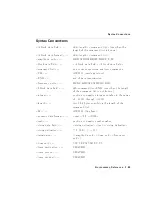
Page 178: ... found under Syntax Conventions unless otherwise speci ed with the key word de nition Square brackets indicate that whatever occurs within the brackets is optional j Or indicates a choice of exactly one element from a list for example a j b indicates a or b but not both Parentheses are used to clarify which elements to choose from Underscore indicates a space must be placed at that location for ex...

Page 179: ...GHZ I block data eld I command list END use when the length of the command list is not known integer positive or negative integer number in the range of 032768 through 32767 length two 8 bit bytes specifying the length of the command list LF ASCII 10 line feed numeric data format real LF EOI real positive or negative real number string data eld string delimiter text string delimiter string delimit...

Page 180: ...upling DB relative decibel unit DBM absolute decibel milliwatt unit DBMV absolute decibel millivolt unit DBUV absolute decibel microvolt unit DM absolute decibel milliwatt unit DN decrement the parameter DSP display E external mixer frequency band EDGE trigger edge EP enable parameter for front panel operator entry EXT external reference mixer mode F external mixer frequency band FAV frequency ana...

Page 181: ...ncy diagnostic M ASCII display data output format MA milliamp unit MAN manual operation MHZ megahertz unit MS millisecond unit MSEC millisecond unit MROLL fractional N frequency frequency diagnostic MV millivolt unit MW milliwatt unit MZ megahertz unit NEG negative peak detection or negative polarity NH next highest NL next left NR next right NRM normal rosenfell detection OA function query same a...

Page 182: ...ostic SR stimulus response sweep time coupling TRA trace A TRB trace B U external mixer frequency band UA microamp unit UNIFORM FFT window format UNPR unpreselected external mixer mode UP increment the parameter UV microvolt unit US microsecond unit V volt unit external mixer frequency band VID video W watt unit external mixer frequency band Y external mixer frequency band ZERO zero span 0 o 1 on ...

Page 183: ...detected Errors labeled AMPL imply amplitude accuracy failure Errors labeled RBW imply resolution bandwidth and amplitude accuracy problems Parameters adjusted after the routine begins and before the fault is detected should be acceptable parameters adjusted later in the sequence are suspect Thus bandwidth values in the error message indicate that the displayed bandwidth or a narrower bandwidth ma...

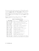
Page 184: ...n Errors Error Message Description ERR 100 NO PWRON Power on state is invalid default state is loaded ERR 101 NO STATE State to be recalled not valid or not saved ERR 106 ABORTED Current operation is aborted GPIB parser reset ERR 107 HELLO No GPIB listener is present ERR 108 TIME OUT Analyzer timed out when acting as controller ERR 109 CtrlFail Analyzer unable to take control of the bus ERR 110 NO...

Page 185: ...guments for this command ERR 132 FAV RMP FAV RAMP are not valid arguments for this command ERR 133 INT EXT INT EXT are not valid arguments for this command ERR 134 ZERO ZERO is not a valid argument for this command ERR 135 CURR CURR is not a valid argument for this command ERR 136 FULL FULL is not a valid argument for this command ERR 137 LAST LAST is not a valid argument for this command ERR 138 ...

Page 186: ... the analyzer thus the normalization is not meaningful ERR 903 A DLMT Part or all of unnormalized trace A is o screen with trace math or normalization on thus part or all of the result is inaccurate ERR 904 B DLMT Part or all of the calibration trace trace B is o screen with trace math or normalization on thus part or all of the result is inaccurate ERR 905 EXT REF Unable to lock Cal Oscillator wh...

Page 187: ...h to obtain a valid channel power bandwidth measurement ERR 920 RBW CHBW The resolution bandwidth is too wide compared to the channel bandwidth to obtain a valid channel power bandwidth measurement The resolution bandwidth should be much less than the channel bandwidth 0 12channel BW ERR 921 AMPCOR Measurement data which would normally be displayed above the top graticule and therefore has unspeci...

Page 188: ......

Page 189: ...A Block Diagrams Block Diagrams A 1 ...

Page 190: ...8560E EC Block Diagram A 2 Block Diagrams ...

Page 191: ...8561E EC Block Diagram Block Diagrams A 3 ...

Page 192: ...8562E EC Block Diagram A 4 Block Diagrams ...

Page 193: ...8563E EC Block Diagram Block Diagrams A 5 ...

Page 194: ...8564E EC Block Diagram A 6 Block Diagrams ...

Page 195: ...8565E EC Block Diagram Block Diagrams A 7 ...

Page 196: ......

Reviews: