Chapter 2
115
Making Measurements
Example 9: Adjacent Channel Power Measurement
Adjacent Channel Power (ACP) Instrument Setup
Settings of the reference level, input attenuation, and display scale are
not changed by the ACP auto measurement function. They must be set
for optimum dynamic range to optimize accuracy.
Although linear and other logarithmic scales are supported, only the
log 10 dB per division scale has adequate dynamic range for ACP
measurements; thus, it should always be used. The reference level (RL)
should be chosen so that the signal exceeds neither the top nor the
bottom of the fidelity-specified range of the chosen (10 dB per division)
scale. When the signals in the channel are CW-like, the optimum RL is
that for which the largest signal is at the RL.
When the signals in the channel are noise-like, as is the case for most
digital modulations, the optimum RL depends on the range of the
logarithmic amplifier and other parameters. The difference between the
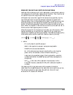
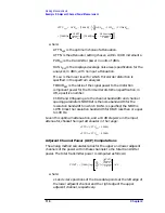
transmitter power and the optimum reference level is given by:
1. where:
P
TX
is the total transmitted power.
RBW is the spectrum analyzer resolution bandwidth.
ChBW is the channel bandwidth.
RL is the reference level power (note that the units must be
power units, for example, mW, and match those of P
TX
).
logrange is the specified range of the log amplifier, a positive
number (100 dB for the 8560 Series and EC-Series Spectrum
Analyzers).
ACP
ratio
is the ratio of the adjacent channel power to the
transmitter power, expressed in dB, and is always a negative
number.
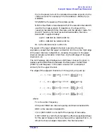
The setting of the input attenuator of the spectrum analyzer
determines the tradeoff between the distortion errors and noise errors.
The following equation expresses the optimum choice of input
attenuation for a spectrum analyzer.
10dB
(
)
log
RL
P
TX
---------
10dB
(
)
log
1.85RBW
ChBW
------------------------
0.439 logrange
ACP
range
+
(
)
+
=
Summary of Contents for 8560E
Page 21: ...21 1 Quick Start Guide ...
Page 48: ...48 Chapter1 Quick Start Guide Manuals Available Separately ...
Page 49: ...49 2 Making Measurements ...
Page 164: ...164 Chapter2 Making Measurements Example 13 Making Pulsed RF Measurements ...
Page 165: ...165 3 Softkey Menus ...
Page 182: ...182 Chapter3 Softkey Menus Menu Trees ...
Page 183: ...183 4 Key Function Descriptions ...
Page 228: ...228 Chapter4 Key Function Descriptions Key Descriptions Figure 4 3 CRT Alignment Pattern ...
Page 289: ...289 5 Programming ...
Page 323: ...Chapter 5 323 Programming Math Functions Figure 5 10 Display Units ...
Page 339: ...339 6 Programming Command Cross Reference ...
Page 369: ...369 7 Language Reference ...
Page 654: ...654 Chapter7 Language Reference VTL Video Trigger Level ...
Page 655: ...655 8 Options and Accessories ...
Page 665: ...665 9 If You Have a Problem ...
Page 674: ...674 Chapter9 If You Have a Problem Power Requirements Figure 9 2 AC Power Cables Available ...

