Chapter 2
117
Making Measurements
Example 9: Adjacent Channel Power Measurement
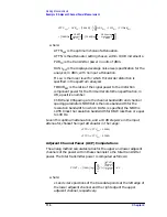
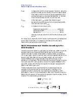
P(x) is the power ratio of the indicated trace data at point x to the
reference level. For example, if the trace data is
−
60 dB, P(x) is
0.000001.
SPAN/600 is the spacing of trace data points.
NBW is the effective noise bandwidth of the resolution bandwidth
used for the measurement. It depends on the shape of the
resolution bandwidth filter, the scale, and the detector mode. For
the ACP function, for most resolution bandwidths, the noise
bandwidth is approximately:
1.128
×
3 dB BW for RBW
≥
300 Hz
1.055
×
3 dB BW for RBW
≤
100 Hz
RL is the reference level in dB units.
The power in the lower adjacent channel is given by the same
expression, except that the upper summation limit is x2, the right edge
of the lower channel, instead of x4. Likewise, the power in the upper
channel includes summation limits from x3, the left edge of the upper
channel, to x4.
The ACP leakage ratio displayed as LOW (lower channel) is given in
decibels as the dB difference between the total power transmitted
(PWR Tx) and the power in the lower channel. UP is computed
similarly for the upper channel.
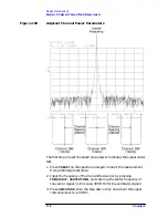
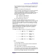
The edges of the adjacent channels, x1 through x4, are given by:
where:
Fc is the center frequency.
ChSp and ChBW are channel spacing and channel bandwidth.
RBW is the resolution bandwidth.
1/2
×
1/600
×
SPAN is one-half of the spacing of trace data.
0.307
×
RBW is a term that changes the effective passband shape
for the power measurement to a shape with a response that is
−
6
dB at the channel edges compared to the channel center.
x1
F
c
ChSp
–
1
2
---
ChBW
–
0.307RBW
1
2
---
1
600
---------
SPAN
+
+
=
x2
F
c
ChSp
–
1
2
---
ChBW
0.307RBW
–
1
2
---
1
600
---------
SPAN
–
+
=
x3
F
c
ChSp
1
2
---
ChBW
–
0.307RBW
1
2
---
1
600
---------
SPAN
+
+
+
=
x4
F
c
ChSp
1
2
---
ChBW
0.307RBW
–
1
2
---
1
600
---------
SPAN
–
+
+
=
Summary of Contents for 8560E
Page 21: ...21 1 Quick Start Guide ...
Page 48: ...48 Chapter1 Quick Start Guide Manuals Available Separately ...
Page 49: ...49 2 Making Measurements ...
Page 164: ...164 Chapter2 Making Measurements Example 13 Making Pulsed RF Measurements ...
Page 165: ...165 3 Softkey Menus ...
Page 182: ...182 Chapter3 Softkey Menus Menu Trees ...
Page 183: ...183 4 Key Function Descriptions ...
Page 228: ...228 Chapter4 Key Function Descriptions Key Descriptions Figure 4 3 CRT Alignment Pattern ...
Page 289: ...289 5 Programming ...
Page 323: ...Chapter 5 323 Programming Math Functions Figure 5 10 Display Units ...
Page 339: ...339 6 Programming Command Cross Reference ...
Page 369: ...369 7 Language Reference ...
Page 654: ...654 Chapter7 Language Reference VTL Video Trigger Level ...
Page 655: ...655 8 Options and Accessories ...
Page 665: ...665 9 If You Have a Problem ...
Page 674: ...674 Chapter9 If You Have a Problem Power Requirements Figure 9 2 AC Power Cables Available ...


