Chapter 2
141
Making Measurements
Example 11: Time-Gated Measurement
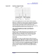
Figure 2-72
Spectrum Analyzer Display
Notice that the gated spectrum is much cleaner than the ungated
spectrum. The spectrum you see is the same as would be seen if the
signal were on continually. To prove this, turn off the pulse modulation
in the signal generator by pressing
SHIFT PULSE OFF
; the spectrum
does not change. In both cases, you can see the two low-level
modulation sidebands caused by the narrow-band FM. Without gating,
these sidebands had been obscured by the pulse spectrum.
Using the Edge Mode and the Level Mode for
Triggering
Depending on the trigger signal that you are working with, you can
trigger the gate in one of two separate modes: edge or level. This
gate-trigger function is separate from the normal external trigger
capability of the spectrum analyzer, which initiates a sweep of a
measurement trace based on an external TTL signal.
Edge Mode
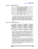
Edge mode lets you position the gate relative to either the rising or
falling edge of a TTL trigger signal. To trigger on the rising edge, press
SWEEP
,
GATED VIDEO
,
GATE CTL LVL EDGE
so that EDGE is underlined,
EDGE POL POS NEG
so that POS is underlined. With the equipment set
up as in the previous example, the oscilloscope screen should appear as
shown in Figure 2-73. By activating
EDGE POL POS NEG
so that NEG is
underlined and decreasing the gate delay, the oscilloscope should
appear as shown in Figure 2-73, where the falling edge initiates the
gate delay.
Summary of Contents for 8560E
Page 21: ...21 1 Quick Start Guide ...
Page 48: ...48 Chapter1 Quick Start Guide Manuals Available Separately ...
Page 49: ...49 2 Making Measurements ...
Page 164: ...164 Chapter2 Making Measurements Example 13 Making Pulsed RF Measurements ...
Page 165: ...165 3 Softkey Menus ...
Page 182: ...182 Chapter3 Softkey Menus Menu Trees ...
Page 183: ...183 4 Key Function Descriptions ...
Page 228: ...228 Chapter4 Key Function Descriptions Key Descriptions Figure 4 3 CRT Alignment Pattern ...
Page 289: ...289 5 Programming ...
Page 323: ...Chapter 5 323 Programming Math Functions Figure 5 10 Display Units ...
Page 339: ...339 6 Programming Command Cross Reference ...
Page 369: ...369 7 Language Reference ...
Page 654: ...654 Chapter7 Language Reference VTL Video Trigger Level ...
Page 655: ...655 8 Options and Accessories ...
Page 665: ...665 9 If You Have a Problem ...
Page 674: ...674 Chapter9 If You Have a Problem Power Requirements Figure 9 2 AC Power Cables Available ...

