148
Chapter 2
Making Measurements
Example 11: Time-Gated Measurement
Video Bandwidth
Just as the resolution-bandwidth filter needs a finite amount of time
to charge and discharge, so does the video filter, which is a
post-detection filter used mainly to smooth the measurement trace.
Regardless of the length of the real RF pulse, the video filter sees a
pulse no longer than the gate length, and the filter will spend part of
that time charging up. To ensure that a true peak value is obtained
before the gate goes off, the video filter must have a charge time of
less than the gate length. For this purpose, you can approximate the
charge time of the video filter as 1/VBW, where VBW is the
−
3 dB
bandwidth of the video filter. Therefore, you will want to be sure
that:
or
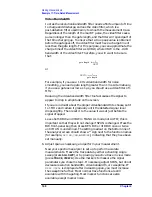
For example, if you use a 1 kHz video bandwidth for noise
smoothing, you need a gate length greater than 1 ms. Alternatively,
if you use a gate as narrow as 1
µ
s, you should use a video filter of 1
MHz.
Reducing the video-bandwidth filter too fast causes the signal to
appear to drop in amplitude on the screen.
If you are in doubt about the proper video bandwidth to choose, set it
to 1 MHz and reduce it gradually until the detected signal level
drops slightly. Then reset it to the value it was at just before the
signal dropped.
Leave both RBW and VBW in MANUAL mode, not AUTO; this is
important so that they will not change if SPAN is changed. Press the
BW front-panel key, then press RES BW or VID BW once or twice
until MAN is underlined. The setting readout on the bottom line of
the analyzer screen should show a "" sign next to the function names
(for example,
RES BW
,
VBW
, and
SWP
), indicating that they have been
set manually.
6. Adjust span as necessary, and perform your measurement.
Now your spectrum analyzer is set up to perform accurate
measurements. Freeze the trace data by either activating single
sweep (press
SGL SWP
), or by placing you active trace in view mode
(press
TRACE
,
VIEW A
). Use the markers to measure the signal
parameters you chose in step 1. If necessary, adjust SPAN, but do not
decrease resolution bandwidth, video bandwidth, or sweeptime. IF
MEAS UNCAL
is displayed after increasing span, you must increase
the sweeptime further. Most normal trace functions are still
available with time-gating. Most marker functions are also
available, except marker noise.
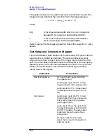
gate length e
1
VBW
-------------
>
VBW
1
gate length
--------------------------
>
Summary of Contents for 8560E
Page 21: ...21 1 Quick Start Guide ...
Page 48: ...48 Chapter1 Quick Start Guide Manuals Available Separately ...
Page 49: ...49 2 Making Measurements ...
Page 164: ...164 Chapter2 Making Measurements Example 13 Making Pulsed RF Measurements ...
Page 165: ...165 3 Softkey Menus ...
Page 182: ...182 Chapter3 Softkey Menus Menu Trees ...
Page 183: ...183 4 Key Function Descriptions ...
Page 228: ...228 Chapter4 Key Function Descriptions Key Descriptions Figure 4 3 CRT Alignment Pattern ...
Page 289: ...289 5 Programming ...
Page 323: ...Chapter 5 323 Programming Math Functions Figure 5 10 Display Units ...
Page 339: ...339 6 Programming Command Cross Reference ...
Page 369: ...369 7 Language Reference ...
Page 654: ...654 Chapter7 Language Reference VTL Video Trigger Level ...
Page 655: ...655 8 Options and Accessories ...
Page 665: ...665 9 If You Have a Problem ...
Page 674: ...674 Chapter9 If You Have a Problem Power Requirements Figure 9 2 AC Power Cables Available ...


