Chapter 4
195
Key Function Descriptions
Key Function Tables
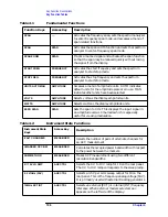
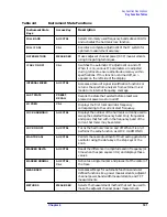
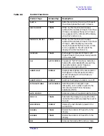
REF LVL ADJ
CAL
Permits adjusting the spectrum analyzer internal gain
so that when the calibrator signal is connected to the
input, the reference level at top screen equals the
calibrator amplitude.
SAMPLER FREQ
CAL
Displays the sampling oscillator frequency and loop
bandwidth compensation value corresponding to the
current start frequency.
SAMPLER HARMONIC
CAL
Displays the sampler harmonic number corresponding
to the current start frequency.
SAVE
—
Accesses a menu for storing instrument data.
SAVE AMPCOR
CAL
Saves the current table of amplitude correction
(ampcor) points.
SAVE PRSEL PK
SAVE
Saves the current preselector peak data in a data
table.
SAVE STATE
SAVE
Displays a menu of ten registers for storing the current
instrument state.
SAVE TRACE A
SAVE
Displays a menu of eight registers for storing trace
contents.
SAVE TRACE B
SAVE
Displays a menu of eight registers for storing trace
contents.
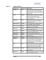
SAVELOCK ON OFF
SAVE
When this function is on, the data in the state and
trace registers cannot be erased or overwritten. No
new data may be entered into the registers until this
function is turned off.
SCROLL CORR PTS
CAL
Allows you to scroll through the list of ampcor
amplitude correction points.
SGL SWP
—
Initiates one sweep and activates single sweep mode.
SIG ID
−
> CF
AUX CTRL
Sets the center frequency to the frequency obtained
from executing SIG ID AT MKR.
SIG ID AT MKR
AUX CTRL
Locates the frequency and harmonic number of the
mixer response where a marker has been positioned.
SIG ID ON OFF
AUX CTRL
Switches manual signal identification on and off.
Signals that are correct for the selected band are
identified by being shifted less than 50 kHz.
SIGNAL IDENT
AUX CTRL
Accesses a menu of signal identification functions.
SINGLE MEASURE
MEAS/USER
Puts the spectrum analyzer in single sweep mode,
completing the current measurement.
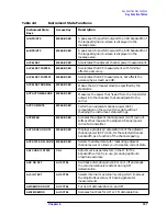
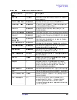
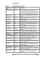
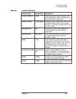
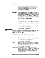
Table 4-2
Instrument State Functions
Instrument State
Keys
Access Key
Description
Summary of Contents for 8560E
Page 21: ...21 1 Quick Start Guide ...
Page 48: ...48 Chapter1 Quick Start Guide Manuals Available Separately ...
Page 49: ...49 2 Making Measurements ...
Page 164: ...164 Chapter2 Making Measurements Example 13 Making Pulsed RF Measurements ...
Page 165: ...165 3 Softkey Menus ...
Page 182: ...182 Chapter3 Softkey Menus Menu Trees ...
Page 183: ...183 4 Key Function Descriptions ...
Page 228: ...228 Chapter4 Key Function Descriptions Key Descriptions Figure 4 3 CRT Alignment Pattern ...
Page 289: ...289 5 Programming ...
Page 323: ...Chapter 5 323 Programming Math Functions Figure 5 10 Display Units ...
Page 339: ...339 6 Programming Command Cross Reference ...
Page 369: ...369 7 Language Reference ...
Page 654: ...654 Chapter7 Language Reference VTL Video Trigger Level ...
Page 655: ...655 8 Options and Accessories ...
Page 665: ...665 9 If You Have a Problem ...
Page 674: ...674 Chapter9 If You Have a Problem Power Requirements Figure 9 2 AC Power Cables Available ...


