Chapter 4
201
Key Function Descriptions
Key Function Tables
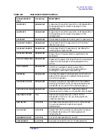
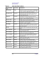
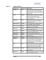
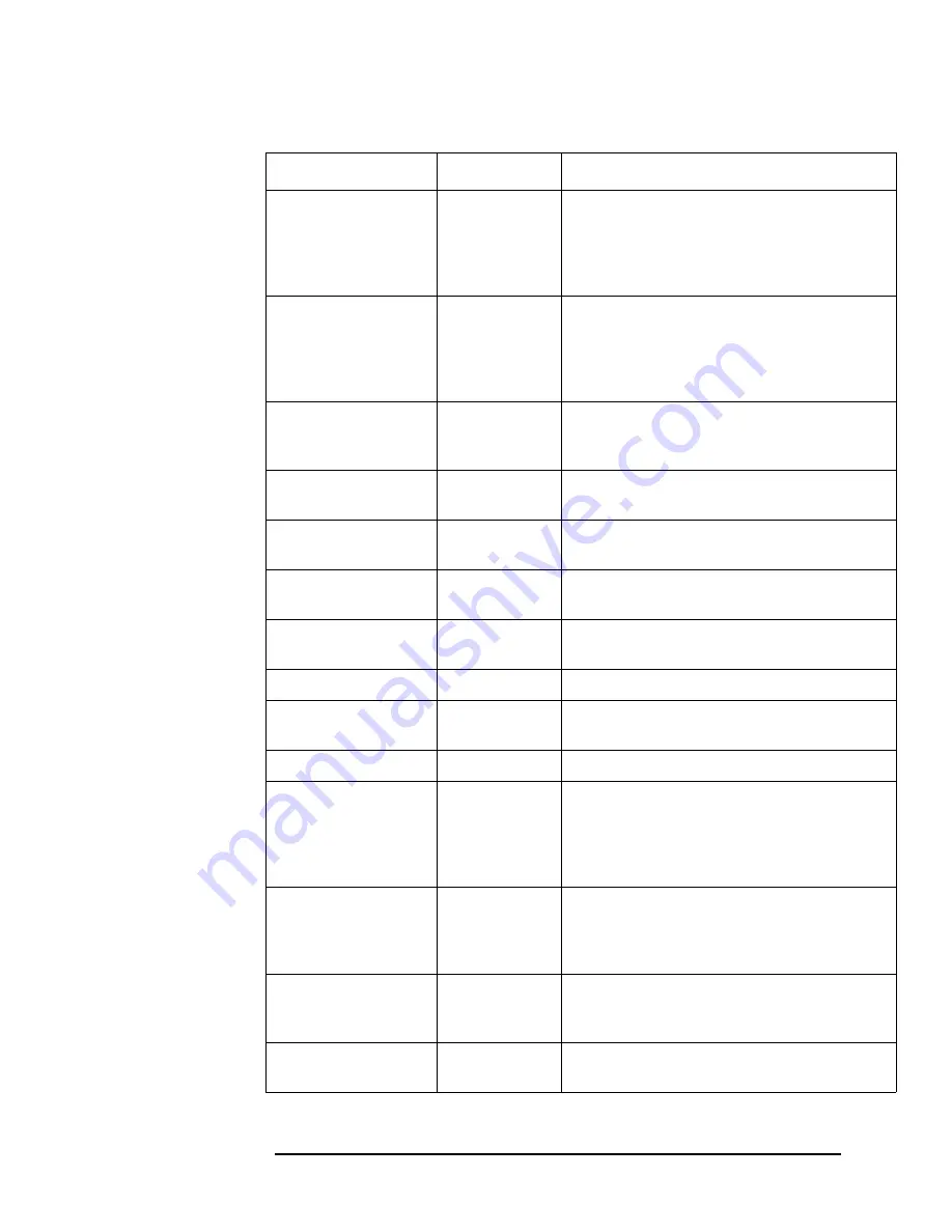
EXTERNAL
TRIG
Sets the trigger to external mode. Connect
external trigger source to J5 (EXT/GATE
TRIG INPUT) on the rear panel. When this
mode is selected, a
T
appears on the left side
of the display.
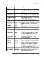
FOCUS
DISPLAY
Permits focusing of the display on E-series
instruments, using the data keys, the step
keys, or the knob.Note: EC-series
instruments do not require adjustment and
are not adjustable.
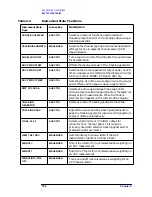
FREE RUN
TRIG
Sets the trigger to free-run mode; sweep
triggers occur as rapidly as the spectrum
analyzer will allow.
FREQ DSP ON OFF
DISPLAY
Turns off all frequency related annotation.
Press
PRESET
to restore annotation.
GATE CTL EDGE LVL
SWEEP
Selects the use of edge triggering or level
triggering to control the gate.
GATE DLY [ ]
SWEEP
Controls the length of time from the trigger
until the gate is turned on.
GATE LEN [ ]
SWEEP
Controls the length of time that the gate is
on when using edge triggering.
GATE ON OFF
SWEEP
Turns the gate function on and off.
GATED VIDEO
SWEEP
Accesses the menu of functions for setting
gate parameters.
GRAT ON OFF
DISPLAY
Turns the display graticule on and off.
INTENSITY
DISPLAY
Permits changing the display intensity on
E-series instruments, using the data keys,
step keys, or the knob. Note: EC-series
instruments do not require adjustment and
are not adjustable.
LINE
TRIG
Sets the trigger to line mode; sweep triggers
occur at intervals synchronized to the line
frequency. When this mode is selected, a
T
appears on the left side of the display.
LVL POL POS NEG
SWEEP
Selects the polarity for turning the gate on
when using level triggering for a gated
measurement.
MAX HOLD A
TRACE
Displays and holds the maximum responses
of the input signal in trace A.
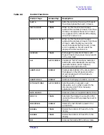
Table 4-4
Control Functions
Control Keys
Access Key
Description
Summary of Contents for 8560E
Page 21: ...21 1 Quick Start Guide ...
Page 48: ...48 Chapter1 Quick Start Guide Manuals Available Separately ...
Page 49: ...49 2 Making Measurements ...
Page 164: ...164 Chapter2 Making Measurements Example 13 Making Pulsed RF Measurements ...
Page 165: ...165 3 Softkey Menus ...
Page 182: ...182 Chapter3 Softkey Menus Menu Trees ...
Page 183: ...183 4 Key Function Descriptions ...
Page 228: ...228 Chapter4 Key Function Descriptions Key Descriptions Figure 4 3 CRT Alignment Pattern ...
Page 289: ...289 5 Programming ...
Page 323: ...Chapter 5 323 Programming Math Functions Figure 5 10 Display Units ...
Page 339: ...339 6 Programming Command Cross Reference ...
Page 369: ...369 7 Language Reference ...
Page 654: ...654 Chapter7 Language Reference VTL Video Trigger Level ...
Page 655: ...655 8 Options and Accessories ...
Page 665: ...665 9 If You Have a Problem ...
Page 674: ...674 Chapter9 If You Have a Problem Power Requirements Figure 9 2 AC Power Cables Available ...

