Chapter 1
31
Quick Start Guide
Making a Basic Measurement
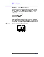
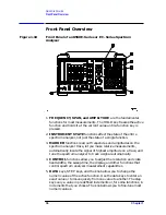
Connect a short cable from the analyzer CAL OUTPUT connector to the
INPUT 50
Ω
connector (both connectors are on the front panel of the
spectrum analyzer). Then perform the following steps:
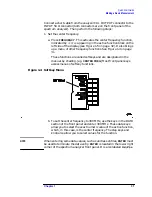
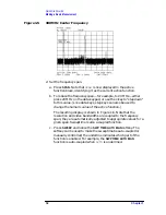
1. Set the center frequency.
a. Press
FREQUENCY
. This activates the center frequency function,
indicated by
CENTER
appearing in the active function block on the
left side of the display (see Figure 1-5 on page 32). It also brings
up a menu of other frequency functions. See Figure 1-4 on page
31.
These functions are called softkeys and are designated in the
manual by shading. (e.g.
CENTER FREQ
) Most front panel keys
access menus of softkey functions.
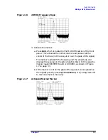
Figure 1-4 Softkey Menu
b. To set the center frequency to 300 MHz, use the keys in the DATA
section of the front panel and enter 300 MHz. These data keys
allow you to select the exact numeric value of the active function,
which, in this case, is the center frequency. The step keys and
knob also allow you to select values for the function.
NOTE
When entering some data values, such as unitless entries,
ENTER
must
be used to terminate the data entry.
ENTER
is located in the lower right
corner of the spectrum analyzer front panel. It is also labeled
Hz/
µ
V/
µ
s
.
Summary of Contents for 8560E
Page 21: ...21 1 Quick Start Guide ...
Page 48: ...48 Chapter1 Quick Start Guide Manuals Available Separately ...
Page 49: ...49 2 Making Measurements ...
Page 164: ...164 Chapter2 Making Measurements Example 13 Making Pulsed RF Measurements ...
Page 165: ...165 3 Softkey Menus ...
Page 182: ...182 Chapter3 Softkey Menus Menu Trees ...
Page 183: ...183 4 Key Function Descriptions ...
Page 228: ...228 Chapter4 Key Function Descriptions Key Descriptions Figure 4 3 CRT Alignment Pattern ...
Page 289: ...289 5 Programming ...
Page 323: ...Chapter 5 323 Programming Math Functions Figure 5 10 Display Units ...
Page 339: ...339 6 Programming Command Cross Reference ...
Page 369: ...369 7 Language Reference ...
Page 654: ...654 Chapter7 Language Reference VTL Video Trigger Level ...
Page 655: ...655 8 Options and Accessories ...
Page 665: ...665 9 If You Have a Problem ...
Page 674: ...674 Chapter9 If You Have a Problem Power Requirements Figure 9 2 AC Power Cables Available ...


