314
Chapter 5
Programming
Data Transfer to Computer
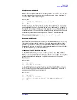
Example 10 uses the I-block format to separate the # and I characters
from the trace data.
E
XAMPLE
10
10
INTEGER Tra_binary(1:601)
20
DIM Header$[2]
30
OUTPUT 718;"IP;CF 300MHZ;SP 20MHZ;SNGLS;TS;"
40
CALL Get_settings(Fa,Fb,Rl,Rb,Vb,St,Lg,Aunits$)
50
OUTPUT 718;"TDF I;TRA?;"
60
ENTER 718 USING "#,2A,601(W)";Header$,Tra_binary(*)
70
END
Like the examples for the A-block format, you store format information
in a string (Header$) and store the desired trace data in an integer
array (Tra_binary).
Returning the trace data to the analyzer requires an important
instruction. The "I" in the term I-block refers to the ability of the
spectrum analyzer to accept data of "indefinite" length when using
I-block format. Even though the analyzer uses only 601 points of trace
data, the I-block format lets you send any number of data points. The
spectrum analyzer will continue to accept data until an
end-of-instruction (EOI) signal is sent to it. HP 9000 Series 200/300
BASIC allows you to send an EOI with the last data byte using the
END command. Refer to Example 11.
E
XAMPLE
11
10
INTEGER Tra_binary(1:601)
20
DIM Header$[2]
30
OUTPUT 718;"IP;CF 300MHZ;SP 20MHZ;SNGLS;TS;"
40
CALL Get_settings(Fa,Fb,Rl,Rb,Vb,St,Lg,Aunits$)
50
OUTPUT 718;"TDF I;TRA?;"
60
ENTER 718 USING "#,2A,601(W)";Header$,Tra_binary(*)
70
PRINT "PRESS CONTINUE TO RETURN DATA TO THE ANALYZER"
80
PAUSE
90
OUTPUT 718;"IP;TS;VIEW TRA;"
100
CALL Setup_analyzer(Fa,Fb,Rl,Rb,Vb,St,Lg,Aunits$)
110
OUTPUT 718;"TDF I;"
120
OUTPUT 718 USING "#,K,601(W)";"TRA#I",Tra_binary(*) END
130
END
By now most of this program should look familiar. Line 120 requires
some explanation, however. The END statement appearing after the
array Tra_binary sends (to the spectrum analyzer) the last data byte
stored in the array, with the GPIB EOI line set "true," as required by
I-block format.
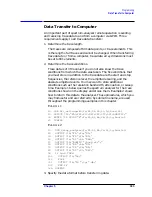
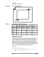
See Table 5-2 on page 315 for an example of how data is sent to the
computer using the TDF I format.
Summary of Contents for 8560E
Page 21: ...21 1 Quick Start Guide ...
Page 48: ...48 Chapter1 Quick Start Guide Manuals Available Separately ...
Page 49: ...49 2 Making Measurements ...
Page 164: ...164 Chapter2 Making Measurements Example 13 Making Pulsed RF Measurements ...
Page 165: ...165 3 Softkey Menus ...
Page 182: ...182 Chapter3 Softkey Menus Menu Trees ...
Page 183: ...183 4 Key Function Descriptions ...
Page 228: ...228 Chapter4 Key Function Descriptions Key Descriptions Figure 4 3 CRT Alignment Pattern ...
Page 289: ...289 5 Programming ...
Page 323: ...Chapter 5 323 Programming Math Functions Figure 5 10 Display Units ...
Page 339: ...339 6 Programming Command Cross Reference ...
Page 369: ...369 7 Language Reference ...
Page 654: ...654 Chapter7 Language Reference VTL Video Trigger Level ...
Page 655: ...655 8 Options and Accessories ...
Page 665: ...665 9 If You Have a Problem ...
Page 674: ...674 Chapter9 If You Have a Problem Power Requirements Figure 9 2 AC Power Cables Available ...


