336
Chapter 5
Programming
Monitoring System Operation
Lines 50 and 60 sends the take-sweep command; during the 10 video
averages that will now occur, the computer remains on line 60. When
the video averaging is complete, TS is complete and the "command
complete" condition is satisfied. The computer then branches to the
subroutine Srq.
Lines 70 and 80 causes the computer to read the decimal equivalent of
the generated service request into the variable Sbyte. The computer
then prints the value, alerting you that the interrupt has occurred.
Line 100 returns the status register to its initial state (that is, no
conditions are masked).
Reading Service Request Data
In the above example, you used the serial-poll statement (SPOLL) to
read the service request data into a variable. The STB (status byte
query) command also reads service request data. Example 2 shows how.
E
XAMPLE
2
10
OUTPUT 718;"IP;SNGLS;CF 300MHZ;SP 20MHZ;TS;"
20
OUTPUT 718;"VAVG 10;RQS 16;"
30
ON INTR 7 GOSUB Srq
40
ENABLE INTR 7;2
50
Done=0
60
OUTPUT 718;"TS;"
70
Idle:
IF Done=0 GOTO Idle
80
STOP
90
Srq:OUTPUT 718;"STB?;";
100
ENTER 718;Sbyte
110
PRINT Sbyte
120
PRINT "VIDEO AVERAGING IS COMPLETE"
130
OUTPUT 718;"RQS 0;"
140
Done=1
150
RETURN
160
END
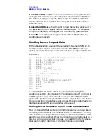
Line 20 sets the bit mask so that only the "command complete"
condition is set. On Line 70, once the "command complete" condition is
satisfied (in this case, after ten video averages), the STB command
queries the spectrum analyzer for the service-request data. The data is
then entered into variable Sbyte and printed. The value returned is the
decimal equivalent of the generated service request.
Reading Service Requests From More Than One Instrument
Most instruments that can be controlled remotely have service request
capability similar to that in the 8560 E-Series and EC-Series. You may
want to take advantage of this capability in other instruments as well
as in the spectrum analyzer. If you have more than one instrument on a
bus that can generate a service request, you need to modify the above
program to look for interrupts from more than one instrument.
Summary of Contents for 8560E
Page 21: ...21 1 Quick Start Guide ...
Page 48: ...48 Chapter1 Quick Start Guide Manuals Available Separately ...
Page 49: ...49 2 Making Measurements ...
Page 164: ...164 Chapter2 Making Measurements Example 13 Making Pulsed RF Measurements ...
Page 165: ...165 3 Softkey Menus ...
Page 182: ...182 Chapter3 Softkey Menus Menu Trees ...
Page 183: ...183 4 Key Function Descriptions ...
Page 228: ...228 Chapter4 Key Function Descriptions Key Descriptions Figure 4 3 CRT Alignment Pattern ...
Page 289: ...289 5 Programming ...
Page 323: ...Chapter 5 323 Programming Math Functions Figure 5 10 Display Units ...
Page 339: ...339 6 Programming Command Cross Reference ...
Page 369: ...369 7 Language Reference ...
Page 654: ...654 Chapter7 Language Reference VTL Video Trigger Level ...
Page 655: ...655 8 Options and Accessories ...
Page 665: ...665 9 If You Have a Problem ...
Page 674: ...674 Chapter9 If You Have a Problem Power Requirements Figure 9 2 AC Power Cables Available ...


