Chapter 1
35
Quick Start Guide
Reference Level Calibration
Reference Level Calibration
Recalibrating the reference level is usually necessary only when the
ambient temperature changes more than 10 degrees Celsius. Because
the spectrum analyzer continually monitors and reduces any IF errors,
executing the reference-level calibration is seldom necessary.
The reference-level calibration function
REF LVL ADJ
allows the
analyzer internal gain to be adjusted. When the calibrator signal is
connected to the input, selecting a reference level equal to the
calibrator amplitude will display the signal at top-screen.
1. Turn the markers off by pressing
MKR
, then
MARKERS OFF
.
2. Press
CAL
. This accesses a menu of calibration routines. The fifth
function on this new list, labeled
REF LVL ADJ
, allows you to
calibrate the amplitude of the instrument.
3. Press
REF LVL ADJ
to activate the function.
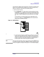
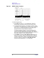
4. To calibrate the spectrum analyzer, use the knob on the front panel
and adjust the peak of the signal to the reference level as shown in
Figure 1-9. Note the number that appears in the active function
block (number 0 in this example). This number ranges from
−
528 to
+528 (
−
33 to +33 in earlier instruments). It is a relative value
indicating how much amplitude correction was required to calibrate
the spectrum analyzer. The number is usually around 0.
If the amplitude is at either end of the range, or if it cannot be
adjusted to a value within this range, consult the calibration guide.
5. To store the value, press the
STORE REF LVL
softkey. When entering
or storing a value using the data keys, the entry must be terminated
with the
ENTER
key, located in the lower-right corner of the analyzer.
Figure 1-9
Peaked Signal to Reference Level
Summary of Contents for 8560E
Page 21: ...21 1 Quick Start Guide ...
Page 48: ...48 Chapter1 Quick Start Guide Manuals Available Separately ...
Page 49: ...49 2 Making Measurements ...
Page 164: ...164 Chapter2 Making Measurements Example 13 Making Pulsed RF Measurements ...
Page 165: ...165 3 Softkey Menus ...
Page 182: ...182 Chapter3 Softkey Menus Menu Trees ...
Page 183: ...183 4 Key Function Descriptions ...
Page 228: ...228 Chapter4 Key Function Descriptions Key Descriptions Figure 4 3 CRT Alignment Pattern ...
Page 289: ...289 5 Programming ...
Page 323: ...Chapter 5 323 Programming Math Functions Figure 5 10 Display Units ...
Page 339: ...339 6 Programming Command Cross Reference ...
Page 369: ...369 7 Language Reference ...
Page 654: ...654 Chapter7 Language Reference VTL Video Trigger Level ...
Page 655: ...655 8 Options and Accessories ...
Page 665: ...665 9 If You Have a Problem ...
Page 674: ...674 Chapter9 If You Have a Problem Power Requirements Figure 9 2 AC Power Cables Available ...


