36
Chapter 1
Quick Start Guide
Front Panel Overview
Front Panel Overview
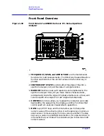
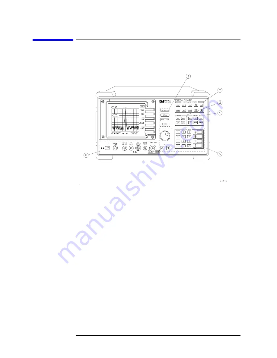
Figure 1-10
Front Panel of an 8560 E-Series or EC- Series Spectrum
Analyzer
1. FREQUENCY, SPAN, and AMPLITUDE are the fundamental
functions for most measurements. The HOLD key freezes the active
function and holds it at the current value until a function key is
pressed.
2. INSTRUMENT STATE functions affect the state of the entire
spectrum analyzer, not just the state of a single function.
3. MARKER functions read out frequencies and amplitudes on the
spectrum analyzer trace, let you make relative measurements,
automatically locate the signal of highest amplitude on a trace, and
tune the spectrum analyzer to track a signal automatically.
4. CONTROL functions allow you to adjust the resolution and video
bandwidths, the sweep time, the display, and other functions that
control spectrum analyzer measurement capabilities.
5. DATA keys, STEP keys, and the knob allow you to change the
numeric value of the active function. Use the data keys to enter an
exact value or to move quickly from one value to another. The step
keys vary a value in predefined increments or, for some functions, in
increments that you choose. The knob allows you to fine-tune most
numeric values.
Summary of Contents for 8560E
Page 21: ...21 1 Quick Start Guide ...
Page 48: ...48 Chapter1 Quick Start Guide Manuals Available Separately ...
Page 49: ...49 2 Making Measurements ...
Page 164: ...164 Chapter2 Making Measurements Example 13 Making Pulsed RF Measurements ...
Page 165: ...165 3 Softkey Menus ...
Page 182: ...182 Chapter3 Softkey Menus Menu Trees ...
Page 183: ...183 4 Key Function Descriptions ...
Page 228: ...228 Chapter4 Key Function Descriptions Key Descriptions Figure 4 3 CRT Alignment Pattern ...
Page 289: ...289 5 Programming ...
Page 323: ...Chapter 5 323 Programming Math Functions Figure 5 10 Display Units ...
Page 339: ...339 6 Programming Command Cross Reference ...
Page 369: ...369 7 Language Reference ...
Page 654: ...654 Chapter7 Language Reference VTL Video Trigger Level ...
Page 655: ...655 8 Options and Accessories ...
Page 665: ...665 9 If You Have a Problem ...
Page 674: ...674 Chapter9 If You Have a Problem Power Requirements Figure 9 2 AC Power Cables Available ...


