Chapter 7
453
Language Reference
DET Detection Modes
DET Detection Modes
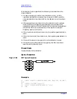
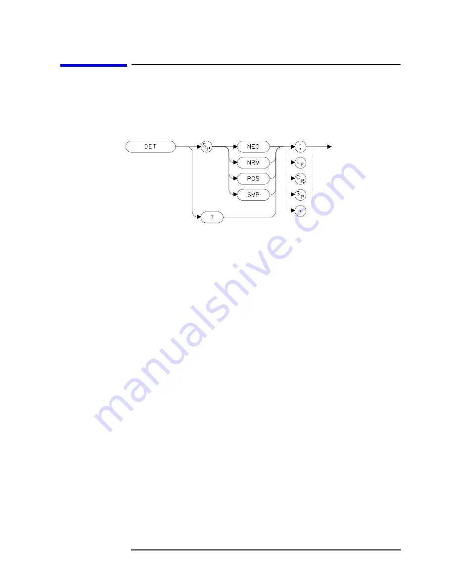
Syntax
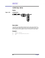
Figure 7-93
DET Syntax
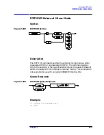
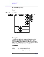
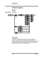
Description
The DET command specifies the IF detector used for acquiring
measurement data. This is normally a coupled function, in which the
spectrum analyzer selects the appropriate detector mode. Four modes
are available: normal, positive, negative, and sample. The modes are
described below. When a mode other than normal is chosen, a
"D"
appears on the left side of the display.
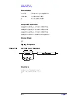
Parameters
NEG
selects the negative peak detector. The minimum signal
values are displayed.
NRM
selects the normal peak detector, which displays both
positive and negative peak values. The noise floor
displayed by alternately selecting positive and negative
peaks. When a signal is encountered, the positive peak
detector is used.
POS
selects the positive peak detector. The maximum signal
values are displayed.
SMP
selects the sample mode, which places the
instantaneous signal value of the analog-to-digital
conversion in memory.
Summary of Contents for 8560E
Page 21: ...21 1 Quick Start Guide ...
Page 48: ...48 Chapter1 Quick Start Guide Manuals Available Separately ...
Page 49: ...49 2 Making Measurements ...
Page 164: ...164 Chapter2 Making Measurements Example 13 Making Pulsed RF Measurements ...
Page 165: ...165 3 Softkey Menus ...
Page 182: ...182 Chapter3 Softkey Menus Menu Trees ...
Page 183: ...183 4 Key Function Descriptions ...
Page 228: ...228 Chapter4 Key Function Descriptions Key Descriptions Figure 4 3 CRT Alignment Pattern ...
Page 289: ...289 5 Programming ...
Page 323: ...Chapter 5 323 Programming Math Functions Figure 5 10 Display Units ...
Page 339: ...339 6 Programming Command Cross Reference ...
Page 369: ...369 7 Language Reference ...
Page 654: ...654 Chapter7 Language Reference VTL Video Trigger Level ...
Page 655: ...655 8 Options and Accessories ...
Page 665: ...665 9 If You Have a Problem ...
Page 674: ...674 Chapter9 If You Have a Problem Power Requirements Figure 9 2 AC Power Cables Available ...


