Chapter 7
503
Language Reference
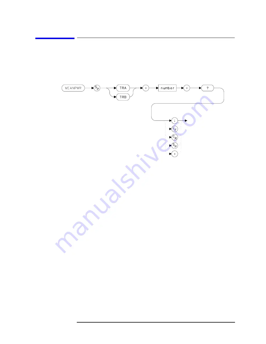
MEANPWR Mean Power Measurement
MEANPWR Mean Power Measurement
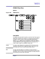
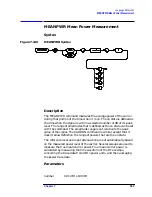
Syntax
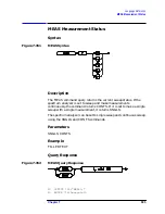
Figure 7-149
MEANPWR Syntax
Description
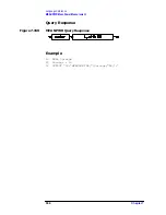
The MEANPWR command measures the average power of the carrier
during that portion of the time when it is on. The on state is defined as
the time when the signal is within a selected number of dB of its peak
level. The range of amplitudes that is defined as the on state can be set
with the command. The amplitude range is set relative to the peak
value of the signal. The CARRON command is similar except that it
doesn't allow definition the range of powers that are the on state.
The reference level and input attenuation are set automatically based
on the measured power level of the carrier. Several sweeps are used to
measure the true mean carrier power. True mean carrier power is
calculated by measuring the time waveform of the RF envelope,
converting the trace data from dB to power units, and then averaging
the power trace data.
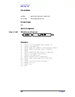
Parameters
number
0.01 dB to 100 dB
Summary of Contents for 8560E
Page 21: ...21 1 Quick Start Guide ...
Page 48: ...48 Chapter1 Quick Start Guide Manuals Available Separately ...
Page 49: ...49 2 Making Measurements ...
Page 164: ...164 Chapter2 Making Measurements Example 13 Making Pulsed RF Measurements ...
Page 165: ...165 3 Softkey Menus ...
Page 182: ...182 Chapter3 Softkey Menus Menu Trees ...
Page 183: ...183 4 Key Function Descriptions ...
Page 228: ...228 Chapter4 Key Function Descriptions Key Descriptions Figure 4 3 CRT Alignment Pattern ...
Page 289: ...289 5 Programming ...
Page 323: ...Chapter 5 323 Programming Math Functions Figure 5 10 Display Units ...
Page 339: ...339 6 Programming Command Cross Reference ...
Page 369: ...369 7 Language Reference ...
Page 654: ...654 Chapter7 Language Reference VTL Video Trigger Level ...
Page 655: ...655 8 Options and Accessories ...
Page 665: ...665 9 If You Have a Problem ...
Page 674: ...674 Chapter9 If You Have a Problem Power Requirements Figure 9 2 AC Power Cables Available ...


