60
Chapter 2
Making Measurements
Example 3: Modulation
Example 3: Modulation
What Is Modulation?
Modulation is the act of translating some low frequency or baseband
signal (voice, music, data) to a higher frequency. In the modulation
process, some characteristic of a carrier signal (usually amplitude or
frequency) is changed in direct proportion to the instantaneous
amplitude of the baseband signal.
More information about amplitude and frequency modulation can be
found in Agilent Technologies Application Note 150-1, literature
number 5954-9130.
Spectrum Analyzer Functions Used
The following procedure describes how to measure signals with AM and
FM types of modulation on them. It shows how to tune the signal onto
the spectrum analyzer display. It demonstrates using the frequency
count function and several marker functions to make measurements.
Stepping Through Modulation Measurements
Amplitude Modulation
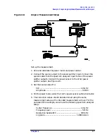
1. Connect the signal source to the spectrum analyzer INPUT 50
Ω
.
2. Set the source to a carrier frequency of 100 MHz with amplitude
modulation of about 34 kHz.
3. Set the spectrum analyzer center frequency to 100 MHz. Set the
span to 500 kHz.
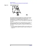
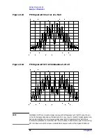
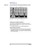
4. Figure 2-7 on page 61 illustrates the amplitude-modulated signal as
seen on the spectrum analyzer display. Note the carrier signal. To
determine its frequency, simply press
PEAK SEARCH
.
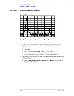
5. Additional modulation information can be easily determined from
the carrier signal and a sideband. For example, the difference
between the carrier frequency and the sideband frequency can be
found by pressing
PEAK SEARCH
,
MARKER DELTA
, and
NEXT PEAK
.
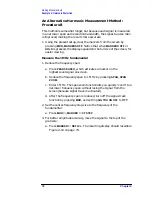
The markers read the frequency difference between the two signals,
which is equal to the modulating frequency. The marker also reads
the difference in amplitude. This difference in amplitude between
the two signals can be used to determine percentage of modulation
(refer to Figure 2-8 on page 61).
Summary of Contents for 8560E
Page 21: ...21 1 Quick Start Guide ...
Page 48: ...48 Chapter1 Quick Start Guide Manuals Available Separately ...
Page 49: ...49 2 Making Measurements ...
Page 164: ...164 Chapter2 Making Measurements Example 13 Making Pulsed RF Measurements ...
Page 165: ...165 3 Softkey Menus ...
Page 182: ...182 Chapter3 Softkey Menus Menu Trees ...
Page 183: ...183 4 Key Function Descriptions ...
Page 228: ...228 Chapter4 Key Function Descriptions Key Descriptions Figure 4 3 CRT Alignment Pattern ...
Page 289: ...289 5 Programming ...
Page 323: ...Chapter 5 323 Programming Math Functions Figure 5 10 Display Units ...
Page 339: ...339 6 Programming Command Cross Reference ...
Page 369: ...369 7 Language Reference ...
Page 654: ...654 Chapter7 Language Reference VTL Video Trigger Level ...
Page 655: ...655 8 Options and Accessories ...
Page 665: ...665 9 If You Have a Problem ...
Page 674: ...674 Chapter9 If You Have a Problem Power Requirements Figure 9 2 AC Power Cables Available ...


