Chapter 9
669
If You Have a Problem
Agilent 85629B Test and Adjustment Module
Agilent 85629B Test and Adjustment Module
The test and adjustment module (TAM) can be used with the 8560E/EC,
Agilent 8561E/EC and Agilent 8563E/EC. A powerful feature of the
TAM is the automatic fault isolation routine. If a problem with the
spectrum analyzer is suspected, in most cases automatic fault isolation
can determine whether or not a fault exists in the analyzer. There are
some problems, such as excessive residual FM, that automatic fault
isolation cannot detect. As a minimum, the display and keyboard must
be operational to execute automatic fault isolation.
Running the Automatic Fault Isolation Routine
To start the automatic fault isolation routine, press
MODULE
and
DIAGNOSE. Rotate the front-panel knob until the arrow points to
Automatic Fault Isolation. Press
EXECUTE
. The CAL OUTPUT must be
connected to the INPUT 50
Ω
. A BNC cable and Type N-to-BNC adapter
is shipped with each analyzer in the front cover. Press CONTINUE, and
the automatic fault isolation routine begins.
The automatic fault isolation routine performs checks of five sections of
the analyzer. Progress of the routine is displayed on the screen. The
routine stops as soon as it detects a failure. If no failures are detected,
the automatic fault isolation routine takes about 90 seconds to
complete.
If a failure is detected, either continue troubleshooting using the
service guide or return the analyzer to the nearest Agilent Technologies
service center as described in "Returning Your Analyzer for Service" in
this chapter. If a GPIB printer is properly connected and configured, a
hard-copy printout of the automatic fault isolation results can be
obtained by pressing
PRINT PAGE
. Include a copy of this printout with
the analyzer if it is being returned to an Agilent Technologies service
center for repair.
Summary of Contents for 8560E
Page 21: ...21 1 Quick Start Guide ...
Page 48: ...48 Chapter1 Quick Start Guide Manuals Available Separately ...
Page 49: ...49 2 Making Measurements ...
Page 164: ...164 Chapter2 Making Measurements Example 13 Making Pulsed RF Measurements ...
Page 165: ...165 3 Softkey Menus ...
Page 182: ...182 Chapter3 Softkey Menus Menu Trees ...
Page 183: ...183 4 Key Function Descriptions ...
Page 228: ...228 Chapter4 Key Function Descriptions Key Descriptions Figure 4 3 CRT Alignment Pattern ...
Page 289: ...289 5 Programming ...
Page 323: ...Chapter 5 323 Programming Math Functions Figure 5 10 Display Units ...
Page 339: ...339 6 Programming Command Cross Reference ...
Page 369: ...369 7 Language Reference ...
Page 654: ...654 Chapter7 Language Reference VTL Video Trigger Level ...
Page 655: ...655 8 Options and Accessories ...
Page 665: ...665 9 If You Have a Problem ...
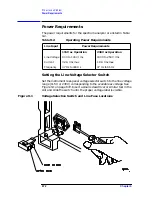
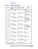
Page 674: ...674 Chapter9 If You Have a Problem Power Requirements Figure 9 2 AC Power Cables Available ...


