78
Chapter 2
Making Measurements
Example 5: Third-Order Intermodulation Distortion
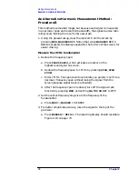
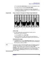
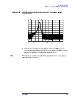
b. Set the reference level to this value by pressing
MKR
→
,
MARKER
→
REF LVL
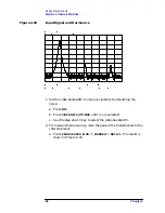
. Figure 2-23 on page 78 illustrates the
resulting display.
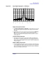
Figure 2-23
Signal Peak Set to Reference Level
Maximize dynamic range
12.Distortion-free dynamic range is important for this type of
measurement. To maximize such dynamic range:
a. Set the mixer input level to
−
30 dBm by pressing
AMPLITUDE
,
MORE 1 OF 3
,
MAX MXR LEVEL
.
b. Enter
−
30 dBm.
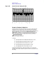
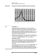
The spectrum analyzer automatically sets the attenuation so the
maximum signal level is
−
30 dBm at the input mixer when the signal is
at or below the reference level (see Example 1). You will hear the input
attenuator click; notice that the value of the attenuator is now 20 dB
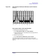
(see Figure 2-24 on page 79).
This change to the maximum mixer level can affect the noise, so you
may need to adjustment the resolution and video bandwidths.
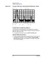
Set a second marker and measure the distortion product
Once a marker is activated, the marker delta function activates a
second marker and displays the difference between the two markers.
Relative measurements can then be performed easily.
Summary of Contents for 8560E
Page 21: ...21 1 Quick Start Guide ...
Page 48: ...48 Chapter1 Quick Start Guide Manuals Available Separately ...
Page 49: ...49 2 Making Measurements ...
Page 164: ...164 Chapter2 Making Measurements Example 13 Making Pulsed RF Measurements ...
Page 165: ...165 3 Softkey Menus ...
Page 182: ...182 Chapter3 Softkey Menus Menu Trees ...
Page 183: ...183 4 Key Function Descriptions ...
Page 228: ...228 Chapter4 Key Function Descriptions Key Descriptions Figure 4 3 CRT Alignment Pattern ...
Page 289: ...289 5 Programming ...
Page 323: ...Chapter 5 323 Programming Math Functions Figure 5 10 Display Units ...
Page 339: ...339 6 Programming Command Cross Reference ...
Page 369: ...369 7 Language Reference ...
Page 654: ...654 Chapter7 Language Reference VTL Video Trigger Level ...
Page 655: ...655 8 Options and Accessories ...
Page 665: ...665 9 If You Have a Problem ...
Page 674: ...674 Chapter9 If You Have a Problem Power Requirements Figure 9 2 AC Power Cables Available ...


