Chapter 2
95
Making Measurements
Example 7: Stimulus-Response Measurements
Using Range Level versus Using Normalized Reference Level
The following example illustrates the difference between
RANGE LVL
and
NORM REF LVL
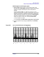
. The normalized frequency response of a
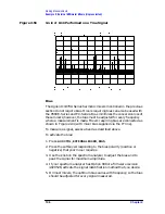
preamplifier is shown in Figure 2-41. The normalized trace is cut off at
the top of the graticule. This is confirmed by the step up
⇓
key when a
marker is activated, and the
ERR 903 A>DLMT
error message appears in
the error message block.
Figure 2-41
Normalized Frequency Response Trace of a Preamplifier
By increasing
NORM REF LVL
to 30 dB, as shown in Figure 2-42, the
trace moves down on the screen. Note that (1) the input attenuator
value remains at 10 dB, (2) the marker-amplitude readout displays 13.2
dB, and (3) the
ERR 903 A>DLMT
error message is still displayed, even
though the signal appears to be fully within the graticule.
Summary of Contents for 8560E
Page 21: ...21 1 Quick Start Guide ...
Page 48: ...48 Chapter1 Quick Start Guide Manuals Available Separately ...
Page 49: ...49 2 Making Measurements ...
Page 164: ...164 Chapter2 Making Measurements Example 13 Making Pulsed RF Measurements ...
Page 165: ...165 3 Softkey Menus ...
Page 182: ...182 Chapter3 Softkey Menus Menu Trees ...
Page 183: ...183 4 Key Function Descriptions ...
Page 228: ...228 Chapter4 Key Function Descriptions Key Descriptions Figure 4 3 CRT Alignment Pattern ...
Page 289: ...289 5 Programming ...
Page 323: ...Chapter 5 323 Programming Math Functions Figure 5 10 Display Units ...
Page 339: ...339 6 Programming Command Cross Reference ...
Page 369: ...369 7 Language Reference ...
Page 654: ...654 Chapter7 Language Reference VTL Video Trigger Level ...
Page 655: ...655 8 Options and Accessories ...
Page 665: ...665 9 If You Have a Problem ...
Page 674: ...674 Chapter9 If You Have a Problem Power Requirements Figure 9 2 AC Power Cables Available ...

