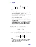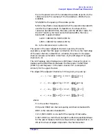
122
Chapter 2
Making Measurements
Example 9: Adjacent Channel Power Measurement
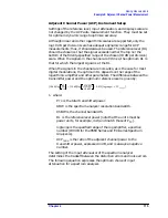
P
wide
is measured with the channel power function, using the
same trace data as was used by the ACP measurement.
That means with the channel power bandwidth set to
(2
×
channel s channel bandwidth), or 792 kHz.
The units should be W, mW, or a similar unit.
P
center
is the same as P
wide
except the channel power
bandwidth should be equal to the channel bandwidth.
Use the same units as P
wide
.
P
carr
is measured in zero span with:
Resolution bandwidth........................
≥
300 kHz
Video bandwidth ...................................... 3 MHz
Sweep time ............................................... 30 ms
Use the units you would like for the final answer, such
as nW.
For many users, the built-in ACP function without all the computations
gives useful information. To measure according to the standard
requires the computations shown above.
NADC Measurements of Mobiles According to the
IS-54 Standard
The following information is applicable as of February 1995. The IS-54
standard requires a measurement method that we call the gated
method. In order to make time-selective measurements, an external
TTL-type trigger input is required when using the gated method. If the
device under test does not have a trigger output, you can use the
Agilent 85902A burst trigger adapter to provide a trigger. This
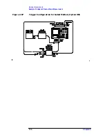
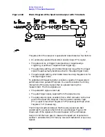
accessory is connected to the signal directly (see Figure 2-56); it may be
more convenient for some users to connect the Agilent 85902A to the
second IF output (310.7 MHz) of a spectrum analyzer equipped with
Option 001. See Figure 2-57.
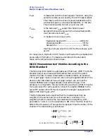
The IS-54 standard also requires that the received spectrum be
weighted in the same manner as it would be in a receiver. The
weighting function used is the root-raised-cosine weighting, with
parameters
T
and
α
.
W
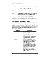
is the weighting in dB. It is a function of
∆
f, the
offset of the frequency of the spectral component from the center of the
channel. The relationship is as follows:
for
∆
f
1
α
–
2T
------------ W
∆
f
( )
0dB
=
,
≤
for
∆
f
1
α
+
2T
------------- W
∆
f
( )
∞
– dB
=
,
≥
for all other
∆
f W
∆
f
( )
10dB
log
10
×
1
2
---
1
π
2
∆
f T
1
–
(
)
2
α
----------------------------------
sin
–
=
,
Summary of Contents for 8560E
Page 21: ...21 1 Quick Start Guide ...
Page 48: ...48 Chapter1 Quick Start Guide Manuals Available Separately ...
Page 49: ...49 2 Making Measurements ...
Page 164: ...164 Chapter2 Making Measurements Example 13 Making Pulsed RF Measurements ...
Page 165: ...165 3 Softkey Menus ...
Page 182: ...182 Chapter3 Softkey Menus Menu Trees ...
Page 183: ...183 4 Key Function Descriptions ...
Page 228: ...228 Chapter4 Key Function Descriptions Key Descriptions Figure 4 3 CRT Alignment Pattern ...
Page 289: ...289 5 Programming ...
Page 323: ...Chapter 5 323 Programming Math Functions Figure 5 10 Display Units ...
Page 339: ...339 6 Programming Command Cross Reference ...
Page 369: ...369 7 Language Reference ...
Page 654: ...654 Chapter7 Language Reference VTL Video Trigger Level ...
Page 655: ...655 8 Options and Accessories ...
Page 665: ...665 9 If You Have a Problem ...
Page 674: ...674 Chapter9 If You Have a Problem Power Requirements Figure 9 2 AC Power Cables Available ...


