142
Chapter 2
Making Measurements
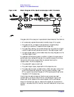
Example 11: Time-Gated Measurement
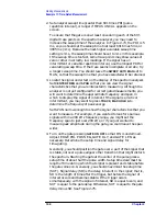
Figure 2-73
Using Positive or Negative Triggering
Level Mode
In level gate-control mode, an external trigger signal opens and closes
the gate directly, without any programmed gate delay or gate length.
Either the TTL high level or TTL low level opens the gate, depending on
the setting of
LVL POL POS NEG
. Therefore, the gate delay and gate
length control functions are not active. Level mode is useful when you
trigger signal occurs at exactly the same time as does the portion of the
signal you want to measure.
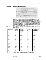
When using level or edge mode, you must set the sweep time, resolution
bandwidth, and video bandwidth as described in “Summary of
Time-Gated Measurement Procedure”.
Stepping through a Time-Gated Measurement
The previous example showed you how to use time-gating to measure a
very specific signal. But most signals requiring time-gating are fairly
complex, so some extra steps are required when performing
measurements. Once you understand the basic steps of time-gated
measurements and the reasons for taking these steps, you will be able
to set up your instruments using just the summary of "rules" or the
recommended control setting tables presented at the end of this
example.
Summary of Contents for 8560E
Page 21: ...21 1 Quick Start Guide ...
Page 48: ...48 Chapter1 Quick Start Guide Manuals Available Separately ...
Page 49: ...49 2 Making Measurements ...
Page 164: ...164 Chapter2 Making Measurements Example 13 Making Pulsed RF Measurements ...
Page 165: ...165 3 Softkey Menus ...
Page 182: ...182 Chapter3 Softkey Menus Menu Trees ...
Page 183: ...183 4 Key Function Descriptions ...
Page 228: ...228 Chapter4 Key Function Descriptions Key Descriptions Figure 4 3 CRT Alignment Pattern ...
Page 289: ...289 5 Programming ...
Page 323: ...Chapter 5 323 Programming Math Functions Figure 5 10 Display Units ...
Page 339: ...339 6 Programming Command Cross Reference ...
Page 369: ...369 7 Language Reference ...
Page 654: ...654 Chapter7 Language Reference VTL Video Trigger Level ...
Page 655: ...655 8 Options and Accessories ...
Page 665: ...665 9 If You Have a Problem ...
Page 674: ...674 Chapter9 If You Have a Problem Power Requirements Figure 9 2 AC Power Cables Available ...


