Chapter 2
157
Making Measurements
Example 12: Making Time-Domain Measurements with Sweep Delay
The following procedure shows how you can use the sweep delay
functions in zero span.
1. Set the center frequency of the spectrum analyzer to the signal of
interest.
2. Set the resolution bandwidth and video bandwidth wider than the
spectral width of the signal of interest. If possible, choose a value
wide enough so that the resolution bandwidth filter is fairly flat over
the width of you signal. (The resolution bandwidth setting indicates
the
−
3 dB width of the filter.)
3. Set the frequency span to 0 Hz.
4. Connect the TTL trigger signal from the device under test to the
BNC connector labeled EXT/GATE TRIG INPUT.
5. Press
TRIG
, and then press
EXTERNAL
.
6. Press
SWEEP
.
7. Press
DLY SWP [ ]
, and then use the data keys or knob to enter the
sweep delay.
8. Press
DLY SWP ON OFF
so that ON is underlined.
9. Set the sweep time so that the duration of the signal is less than the
sweep time.
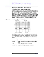
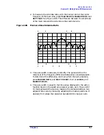
The sweep delay functions allow you to see the full pulse width. See
Figure 2-82. The sweep delay functions can be used for non-zero spans,
as well as time-gated measurements. When the sweep delay is used
during a time-gated measurement, the sweep delay and the gate delay
are not summed together. For example, if the pulse occurred 60 ms after
the trigger signal, you would set the sweep delay to 58 ms and the gate
delay to 60 ms.
Summary of Contents for 8560E
Page 21: ...21 1 Quick Start Guide ...
Page 48: ...48 Chapter1 Quick Start Guide Manuals Available Separately ...
Page 49: ...49 2 Making Measurements ...
Page 164: ...164 Chapter2 Making Measurements Example 13 Making Pulsed RF Measurements ...
Page 165: ...165 3 Softkey Menus ...
Page 182: ...182 Chapter3 Softkey Menus Menu Trees ...
Page 183: ...183 4 Key Function Descriptions ...
Page 228: ...228 Chapter4 Key Function Descriptions Key Descriptions Figure 4 3 CRT Alignment Pattern ...
Page 289: ...289 5 Programming ...
Page 323: ...Chapter 5 323 Programming Math Functions Figure 5 10 Display Units ...
Page 339: ...339 6 Programming Command Cross Reference ...
Page 369: ...369 7 Language Reference ...
Page 654: ...654 Chapter7 Language Reference VTL Video Trigger Level ...
Page 655: ...655 8 Options and Accessories ...
Page 665: ...665 9 If You Have a Problem ...
Page 674: ...674 Chapter9 If You Have a Problem Power Requirements Figure 9 2 AC Power Cables Available ...


