Chapter 4
285
Key Function Descriptions
Key Descriptions
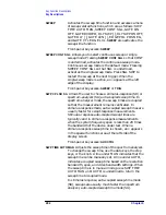
TRIG
Accesses a menu of trigger functions: SWEEP CONT
SGL, FREE RUN, VIDEO, LINE, EXTERNAL, and
TRIG POL POS NEG. When any mode other than
FREE RUN is selected, a
T
appears in the special
functions area at the left side of the display screen.
Front-panel key access:
TRIG
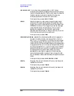
TRIG POL POS NEG
Sets the sweep to trigger on the rising edge (POS)
or the falling edge (NEG) of the trigger signal.
Front-panel key access:
TRIG
UNITS AUTO MAN
Selects amplitude units automatically (AUTO) or
manually (MAN). When in AUTO mode, the default
units are dBm (in log scale) or VOLTS (in linear scale).
The units available from this menu are: dBm, dB
µ
V,
dBmV, VOLTS, WATTS.
Front-panel key access:
AMPLITUDE
or
AUTO COUPLE
VBW/RBW RATIO
Displays the current coupling ratio between the video
bandwidth and the resolution bandwidth. The ratio is
displayed in the active function block, and is used when
the two bandwidths are in coupled mode. The ratio
ranges from 0.003 to 3, in a 1, 3, 10 sequence. The
default value is 1.
Front-panel key access:
BW
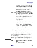
V/GHz .25 .50
For Agilent 8564E/EC and Agilent 8565E/EC only.
Specifies a 0.25 or 0.5 volts per GHz sweep output at
the rear-panel connector J8. This is also referred to as
the frequency analog voltage (FAV). Connector J8 is
labeled LO SWP|FAV OUTPUT. When using a 8560
E-Series or EC-Series with a tracking generator such as
an Agilent 85640A, this softkey must be activated and
set to 0.5 V/GHz. Pressing
PRESET
does not change the
selection of FAV as the output for J8.
If the preselected external mixer mode is selected,
rear-panel output J8 is automatically switched to the
0.5 V/GHz (FAV) mode. The actual output at J8
becomes 1.5 V/GHz, referenced to the LO frequency.
The 1.5 V/GHz of the LO frequency is required for the
Agilent 11974 Series preselected external mixers.
Front-panel key access:
AUX CTRL
Summary of Contents for 8560E
Page 21: ...21 1 Quick Start Guide ...
Page 48: ...48 Chapter1 Quick Start Guide Manuals Available Separately ...
Page 49: ...49 2 Making Measurements ...
Page 164: ...164 Chapter2 Making Measurements Example 13 Making Pulsed RF Measurements ...
Page 165: ...165 3 Softkey Menus ...
Page 182: ...182 Chapter3 Softkey Menus Menu Trees ...
Page 183: ...183 4 Key Function Descriptions ...
Page 228: ...228 Chapter4 Key Function Descriptions Key Descriptions Figure 4 3 CRT Alignment Pattern ...
Page 289: ...289 5 Programming ...
Page 323: ...Chapter 5 323 Programming Math Functions Figure 5 10 Display Units ...
Page 339: ...339 6 Programming Command Cross Reference ...
Page 369: ...369 7 Language Reference ...
Page 654: ...654 Chapter7 Language Reference VTL Video Trigger Level ...
Page 655: ...655 8 Options and Accessories ...
Page 665: ...665 9 If You Have a Problem ...
Page 674: ...674 Chapter9 If You Have a Problem Power Requirements Figure 9 2 AC Power Cables Available ...


