304
Chapter 5
Programming
Data Transfer to Computer
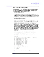
Use the TDF (trace data format) command to specify the format
before sending data from the spectrum analyzer to the computer.
The examples in this section illustrate how to use this command.
The examples in this section use the ] (trace A) command. This
command transfers data to and from trace A. The TRB (trace B)
command is also available for transferring trace B data. It is possible
to read data from trace A and then send it to trace B, and also to
read data from trace B and send it to trace A. For simplicity, this
capability is not reflected in the programming examples in this
section.
The analyzer returns information as decimal values in fundamental
units shown in Table 5-1. The analyzer does not automatically apply
these units to data received from the computer; the user must specify
the units.
As indicated in Table 5-1, power and amplitude information can be
returned in several different units. The AUNITS (amplitude units)
command is used to select the desired unit. The AUNITS command can
either specify a single unit to be used for all power and amplitude
information, or it can be set to automatically select the units, based on
certain measurement settings. Refer to the description of the AUNITS
command in Chapter 7 of this manual for more information.
Parameter Units versus Measurement Units
All units referred to above are parameter units, which are standard
scientific units. Trace data can optionally be sent to and received from
the analyzer in non-standard units, measurement units, which are
used internally by the analyzer. The main advantage to communicating
with the analyzer in measurement units is speed; when the analyzer
communicates in parameter units, it must convert between internal
measurement units and parameter units.
Table 5-1
Units for Returned Data
Measured
Data
Fundamental Unit
Frequency
Hz
Power
dBm, dBmV, dB
µ
V, W
Amplitude
dBm, dBmV, dB
µ
V, W, V
Ratio
dB, unitless (voltage ratio)
Voltage
V
Time
s
Summary of Contents for 8560E
Page 21: ...21 1 Quick Start Guide ...
Page 48: ...48 Chapter1 Quick Start Guide Manuals Available Separately ...
Page 49: ...49 2 Making Measurements ...
Page 164: ...164 Chapter2 Making Measurements Example 13 Making Pulsed RF Measurements ...
Page 165: ...165 3 Softkey Menus ...
Page 182: ...182 Chapter3 Softkey Menus Menu Trees ...
Page 183: ...183 4 Key Function Descriptions ...
Page 228: ...228 Chapter4 Key Function Descriptions Key Descriptions Figure 4 3 CRT Alignment Pattern ...
Page 289: ...289 5 Programming ...
Page 323: ...Chapter 5 323 Programming Math Functions Figure 5 10 Display Units ...
Page 339: ...339 6 Programming Command Cross Reference ...
Page 369: ...369 7 Language Reference ...
Page 654: ...654 Chapter7 Language Reference VTL Video Trigger Level ...
Page 655: ...655 8 Options and Accessories ...
Page 665: ...665 9 If You Have a Problem ...
Page 674: ...674 Chapter9 If You Have a Problem Power Requirements Figure 9 2 AC Power Cables Available ...


