Chapter 5
313
Programming
Data Transfer to Computer
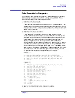
To send trace data from the computer to the analyzer, refer to Example
9.
E
XAMPLE
9
10
INTEGER Tra_binary(1:601)
20
DIM Header$[4]
30
OUTPUT 718;"IP;CF 300MHZ;SP 20MHZ;SNGLS;TS;"
40
CALL Get_settings(Fa,Fb,Rl,Rb,Vb,St,Lg,Aunits$)
50
OUTPUT 718;"TDF A;TRA?;"
60
ENTER 718 USING "#,4A,601(W)";Header$,Tra_binary(*)
70
PRINT "PRESS CONTINUE TO RETURN DATA TO THE ANALYZER"
80
PAUSE
90
OUTPUT 718;"IP;TS;VIEW TRA;"
100
CALL Setup_analyzer(Fa,Fb,Rl,Rb,Vb,St,Lg,Aunits$)
110
OUTPUT 718;"TDF A;"
120
OUTPUT 718 USING
"#,K,W,601(W)";"TRA#A",1202,Tra_binary(*),";"
130
END
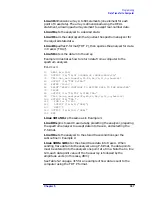
Line 90 presets the analyzer and sets trace A to view mode.
Line 100 returns the state data to the analyzer.
Line 110 sets the data format to A-block.
Line 120 sends the TRA command, the format information, and the
trace data. The USING statement specifies that the data "TRA#A" will
be sent as characters, followed by a word (1202) and 601 16-bit words
(the actual trace data). Remember, you must send #A to indicate the
format and 1202 to indicate the length of the trace, in bytes. The "#"
sign within the USING statement suppresses any end-of-line signal
characters.
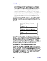
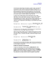
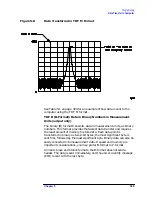
See Table 5-2 on page 315 for an example of how data is sent to the
computer using the TDF A format.
TDF I (I-block format): Return Indefinite Block-Data Fields in
Measurement Units
Very similar to A-block format, the I-block format transmits data in
measurement units as binary numbers in an indefinite block-data field
of unknown size. Each data point is sent as two 8-bit bytes; the most
significant byte is sent first, followed by the least significant byte. The
I-block format also transfers a header before the trace data. The header
is comprised of ASCII characters "#", and "I". These characters indicate
that the trace data is in I-block format. Like the A-block format
examples, when sending the trace data to the computer, you may want
to keep these two characters separate from the trace data, as in
Example 10.
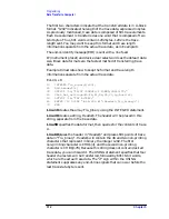
I-format sends an end-or-identify message (EOI) with the last byte of
data. IP (instrument preset) and device clear select words as the default
data size. Block data formats are the fastest method of transferring
trace data.
Summary of Contents for 8560E
Page 21: ...21 1 Quick Start Guide ...
Page 48: ...48 Chapter1 Quick Start Guide Manuals Available Separately ...
Page 49: ...49 2 Making Measurements ...
Page 164: ...164 Chapter2 Making Measurements Example 13 Making Pulsed RF Measurements ...
Page 165: ...165 3 Softkey Menus ...
Page 182: ...182 Chapter3 Softkey Menus Menu Trees ...
Page 183: ...183 4 Key Function Descriptions ...
Page 228: ...228 Chapter4 Key Function Descriptions Key Descriptions Figure 4 3 CRT Alignment Pattern ...
Page 289: ...289 5 Programming ...
Page 323: ...Chapter 5 323 Programming Math Functions Figure 5 10 Display Units ...
Page 339: ...339 6 Programming Command Cross Reference ...
Page 369: ...369 7 Language Reference ...
Page 654: ...654 Chapter7 Language Reference VTL Video Trigger Level ...
Page 655: ...655 8 Options and Accessories ...
Page 665: ...665 9 If You Have a Problem ...
Page 674: ...674 Chapter9 If You Have a Problem Power Requirements Figure 9 2 AC Power Cables Available ...

