40
Chapter 1
Quick Start Guide
Front Panel Overview
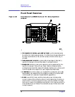
14.Active special functions: the following characters appear in a
vertical line alongside the graticule. This information is also
available by pressing
DISPLAY
, then
ANNOT HELP
.
15.Active function area
16.Message area (for example, messages such as
MEAS UNCAL
,
PEAKING
,
and
Sampling
are displayed in the message area)
17.Marker indicator
18.Indicator of reference-level position when in normalized mode
19.Reference level
20.Input attenuator value (internal mixing) or conversion loss (external
mixing)
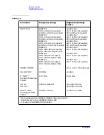
Table 1-3
A =
IF adjust turned OFF
C =
DC coupling selected (The 8563E/EC, 8564E/EC, and 8565E/EC
are always dc coupled. AC coupling is available only for an
8560E/EC, 8561E/EC or 8562E/EC spectrum analyzers. The
default setting for an 8560E/EC, 8561E/EC or 8562E/EC is ac
coupling.)
D =
Detector mode set to sample, negative peak, or positive peak
E =
Special sweep-time equations in use (refer to tracking generator
menus)
F =
Frequency offset is less than or greater than 0 Hz
G =
Internal tracking generator is ON
K =
Signal track is ON
M =
Trace math is ON
N =
Normalization is ON
R =
Reference level offset is less than or greater than 0 dB
S =
Single-sweep mode
T =
Trigger mode set to line, video, or external
W =
Amplitude correction (ampcor) is on
X =
10 MHz reference is external
+ =
External mixer bias is greater than 0 mA
−
=
External mixer bias is less than 0 mA
Summary of Contents for 8560E
Page 21: ...21 1 Quick Start Guide ...
Page 48: ...48 Chapter1 Quick Start Guide Manuals Available Separately ...
Page 49: ...49 2 Making Measurements ...
Page 164: ...164 Chapter2 Making Measurements Example 13 Making Pulsed RF Measurements ...
Page 165: ...165 3 Softkey Menus ...
Page 182: ...182 Chapter3 Softkey Menus Menu Trees ...
Page 183: ...183 4 Key Function Descriptions ...
Page 228: ...228 Chapter4 Key Function Descriptions Key Descriptions Figure 4 3 CRT Alignment Pattern ...
Page 289: ...289 5 Programming ...
Page 323: ...Chapter 5 323 Programming Math Functions Figure 5 10 Display Units ...
Page 339: ...339 6 Programming Command Cross Reference ...
Page 369: ...369 7 Language Reference ...
Page 654: ...654 Chapter7 Language Reference VTL Video Trigger Level ...
Page 655: ...655 8 Options and Accessories ...
Page 665: ...665 9 If You Have a Problem ...
Page 674: ...674 Chapter9 If You Have a Problem Power Requirements Figure 9 2 AC Power Cables Available ...


