676
Chapter 9
If You Have a Problem
Procedures
Reference Level Calibration
1. Press
PRESET
.
2. Connect a 50
Ω
coaxial cable (such as Agilent 10503A) between the
front-panel CAL OUTPUT and INPUT 50
Ω
connectors.
3. Set the analyzer center frequency to 300 MHz by pressing
FREQUENCY
300
MHz
.
4. Set the analyzer span to 20 MHz by pressing
SPAN
20
MHz
.
5. Press
PEAK SEARCH
.
6. Set the analyzer reference level to
−
10 dBm by pressing
AMPLITUDE
10
−
dBm
.
7. Press
CAL
,
REF LVL ADJ
.
8. Rotate the analyzer front-panel knob until the
MKR
reading is
−
10.00
dBm
±
0.17 dB. There is a slight delay in time between adjusting the
knob and the change in marker value. Notice that the displayed REF
LEVEL CAL value changes. The
REF LVL CAL
value should range
between
−
528 and +528 (
−
33 to +33 with firmware revisions
≤
920528).
9. Press
STORE REF LVL
.
10.Press
PRESET
.
GPIB Address Selection
1. The GPIB address for the analyzer is preset at the factory to a
decimal value of 18. Valid addresses range from 0 to 30. To view the
GPIB address, press
PRESET CONFIG
,
ANALYZER ADDRESS
.
2. To change the address value, enter the new address number using
the front-panel data keys. Terminate the entry by pressing a units
key. For example, enter an address of 18 by pressing the
PRESET
CONFIG
,
ANALYZER ADDRESS
, 18
Hz
.
3. Press
STORE HPIB ADR
.
4. Press
PRESET
.
With the GPIB address set and trace alignment and reference level
calibration procedures successfully completed, the analyzer is ready for
normal operation.
Summary of Contents for 8560E
Page 21: ...21 1 Quick Start Guide ...
Page 48: ...48 Chapter1 Quick Start Guide Manuals Available Separately ...
Page 49: ...49 2 Making Measurements ...
Page 164: ...164 Chapter2 Making Measurements Example 13 Making Pulsed RF Measurements ...
Page 165: ...165 3 Softkey Menus ...
Page 182: ...182 Chapter3 Softkey Menus Menu Trees ...
Page 183: ...183 4 Key Function Descriptions ...
Page 228: ...228 Chapter4 Key Function Descriptions Key Descriptions Figure 4 3 CRT Alignment Pattern ...
Page 289: ...289 5 Programming ...
Page 323: ...Chapter 5 323 Programming Math Functions Figure 5 10 Display Units ...
Page 339: ...339 6 Programming Command Cross Reference ...
Page 369: ...369 7 Language Reference ...
Page 654: ...654 Chapter7 Language Reference VTL Video Trigger Level ...
Page 655: ...655 8 Options and Accessories ...
Page 665: ...665 9 If You Have a Problem ...
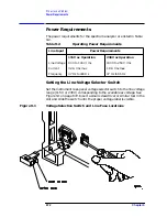
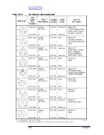
Page 674: ...674 Chapter9 If You Have a Problem Power Requirements Figure 9 2 AC Power Cables Available ...

